Access Control has been a booming part of the security industry, and within the last year we started to dabble in it ourselves. We have written several articles on wiring as well as how to configure the software, so this article’s purpose will not be demonstrating that. I will show a bit of wiring, but my main goal with this article is to connect a 2 Door DX Access Control Board to a 32 CH DVR we have in our office. You may be familiar with the alarm inputs of the DVR or you may not, makes no difference. The reasoning for connecting this board to the alarm inputs on the DVR is simple. For example, you might have a side door to your building and you want to know every time someone enters or exits it. It may not be practical to have the live recording showing all the time that shows you when a card is scanned via the DX software. If you had an entire security system from us including cameras and a DVR, you could mount a camera on both sides of this door and every time someone enters or exits have the camera blow up full screen on your monitor. Well, what if I am busy and not watching the monitor? I can show you how you can also have the camera send a snapshot to your email when someone swipes a card or pushes the push to exit.
Keep in mind that the reader and push to exit are on opposite sides of the door, so you will have to configure this in a way where when either is used to enter or leave you get a snapshot of both cameras, outside and inside, and the DVR will start to record on both channels as well. It is easy so lets get into it.
PLEASE, BY NO MEANS AT ALL, DO NOT LET A MAG LOCK OR DOOR STRIKE BE YOUR ONLY MEANS OF SECURITY. A DEAD BOLT OR LOCKING THE DOOR HANDLE WILL STILL BE NECESSARY!
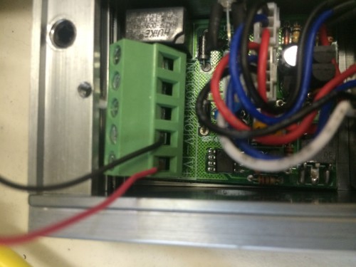
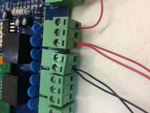
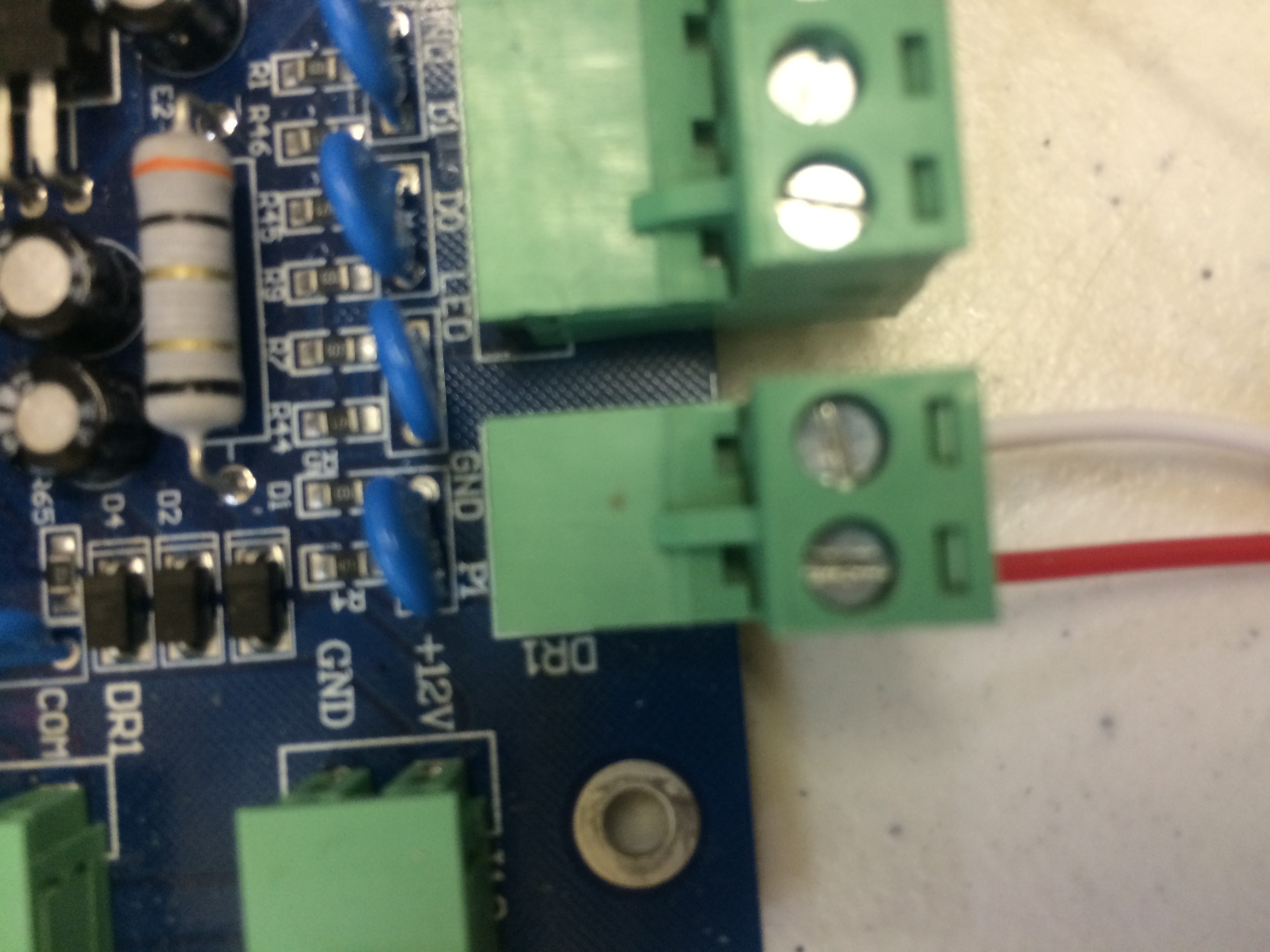
First, you need to wire the access control system, and you can see a picture representing my explanation below. I have 12v power coming into the board powering the entire board, and it will also power the lock and the push to exit as well. Then I have a jumper going from 12V+ to the COM (Common) port for DR1 (Door 1). This jumper powers the pole in that relay for your NO (Normally Open) or NC (Normally Closed) Device for DR1. The mag lock I used is a NC device so I then have a wire running from the NC of DR1 to the 12v+ of the lock. Then there is another wire running from DR1 GND(Ground) to the 12V- of the lock. This gets power to your lock through the board and allows it to be controlled as a NC device.
Now, you need to have the reader setup and access allowed in the software for your card or fob. As I said before, this article is not to teach you how to wire, I am assuming you have the reader hooked up, and at this point the lock wired and access granted within your software for your fob.
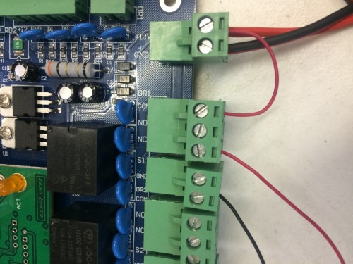
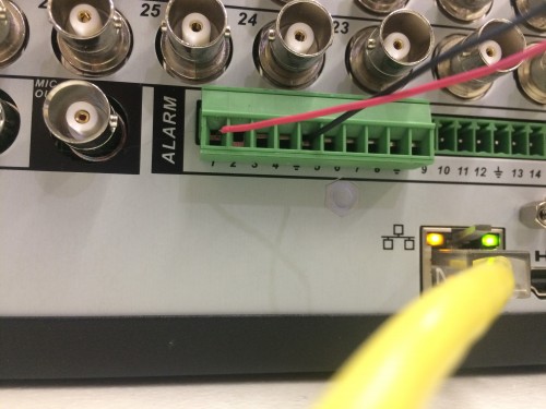
Now we need to get the access control board wired to the DVR. This is exactly the same as wiring the lock to the board. You will run a wire from the NC of DR1 on the board to the first alarm input on the back of the DVR. Then run a wire from the GND of DR1 on the board to the ground a few spaces to the right of the alarm in on the DVR. That is all that needs to be wired to the DVR for this to work. Easy, right? See Below.
Now all that needs to be done is to wire the push to exit to the board. The one I am using uses the red wire for normally open, and the white wire is for COM. You need to run the NO from the push to exit to a block to the right of the 12V+- for the board so the NO of the exit button goes to P1 (Push 1), then the COM for the exit button runs to the GND to the right of P1.
Now all that is left is to configure the DVR to do what you want it to do. I have my DVR configured to have channel 1 go full screen when the reader or push to exit are used, and I will also have an email with a snapshot be sent to my email. The way you need to do this is to go into the main menu and find the alarm tab, then you will need to configure the alarm input#1. The event type will be “Local Alarm” and set for alarm in 1, and for this scenario it is a NC Device. Then we will set “Record Channel” to 1 and 2. This way both cameras on both sides of the door record. Then for the two channels to go full screen you need to enable the tour under display, but make sure the only tour selected is for 36 view in this case. Ultimately, you need to enable the tour and have only the full camera grid selected so 16 if its a 16 channel so on so forth. Then, back under the alarm tab enable tour and select channels 1 and 2, or which ever two channels are on this door. Then when the lock releases it will go from all cams to channel 1 then after 5 seconds switch to channel 2 then after another 5 seconds it will go back to all cameras. For email, make sure the email page is configured and once it is, under alarm enable snapshot and “send email” then select the two channels you need the snapshots from and you are all set. Please review all my pictures and make sure everything is configured correctly. If you need any help with a setup of your own please feel free to contact our support at (866) 573-8878 option 3 and we will be more than happy to help you.