Your cart is currently empty!
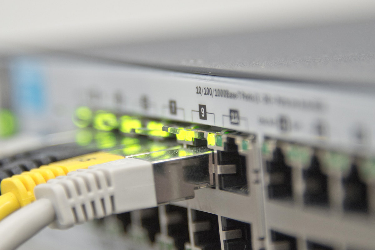
How to Connect an Ethernet Cable to a Security Camera
[vc_section][vc_row][vc_column][vc_column_text]Connecting an Ethernet cable to a security camera is essential for establishing a reliable network connection, ensuring data transmission, and often providing power via Power over Ethernet (PoE). Here’s a step-by-step guide:
Step 1: Gather Necessary Equipment
- Ethernet Cable (Cat5e or Cat6): Ensure you have a sufficient length of Ethernet cable.
- RJ45 Connectors: You’ll need RJ45 connectors to terminate the Ethernet cable.
- Crimping Tool: A crimping tool is necessary for attaching the RJ45 connectors to the cable.
- Security Camera with Ethernet Port: Ensure your security camera has an Ethernet port.
- Network Switch or PoE Injector: For connecting the camera to your network. If using PoE, ensure the switch or injector supports it.
Step 2: Prepare the Ethernet Cable
- Measure and Cut: Measure the distance between your camera and the network switch or NVR. Cut the Ethernet cable to the desired length.
- Strip the Cable: Use a cable stripper to remove about 1 inch of the outer insulation from both ends of the cable, exposing the twisted pairs of wires inside.
Step 3: Arrange and Insert Wires
- Untwist and Arrange Wires: Untwist the pairs and arrange them in the correct order. The standard wiring configuration is T568B:
- White/Orange
- Orange
- White/Green
- Blue
- White/Blue
- Green
- White/Brown
- Brown
- Cut Wires Evenly: Ensure all wires are cut to an even length.
Step 4: Attach RJ45 Connectors
- Insert Wires into RJ45 Connector: Hold the RJ45 connector with the clip facing down. Carefully insert the wires into the connector, ensuring each wire goes into its corresponding slot.
- Crimp the Connector: Use a crimping tool to crimp the RJ45 connector onto the cable. This secures the connection and ensures good contact.
Step 5: Connect the Camera
- Plug the RJ45 Connector: Insert the crimped RJ45 connector into the Ethernet port on the security camera.
- Connect to Network Switch: Plug the other end of the Ethernet cable into the network switch or NVR.
Step 6: Power the Camera
- PoE (Power over Ethernet): If using PoE, the camera will receive power through the same Ethernet cable. Ensure your switch or injector supports PoE.
- Separate Power Supply: If not using PoE, connect the camera to a separate power source using its power adapter.
Step 7: Configure the Camera
- Network Settings: Access the camera’s settings via its web interface or software provided by the manufacturer. Ensure the camera is properly configured with the correct IP address and network settings.
- Test the Connection: Verify that the camera is working by viewing the live feed on your monitor or NVR.
[/vc_column_text][/vc_column][/vc_row][vc_row][vc_column][/vc_column][/vc_row][vc_row][vc_column][vc_separator][/vc_column][/vc_row][/vc_section][vc_section][vc_row][vc_column][vc_column_text]
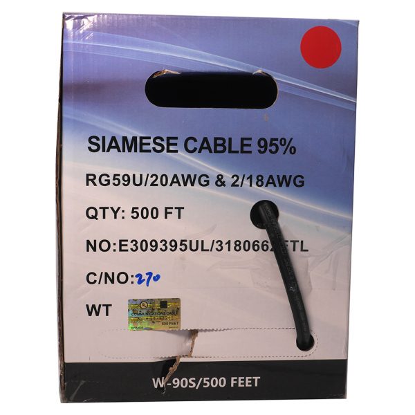
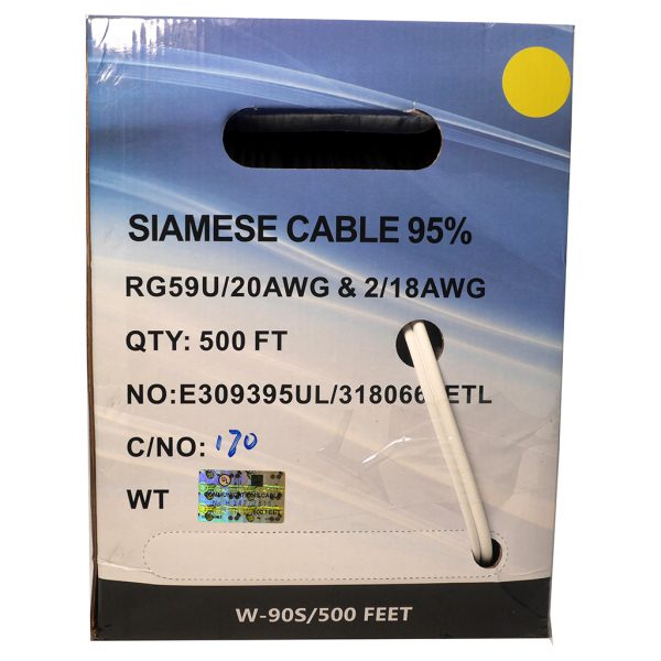
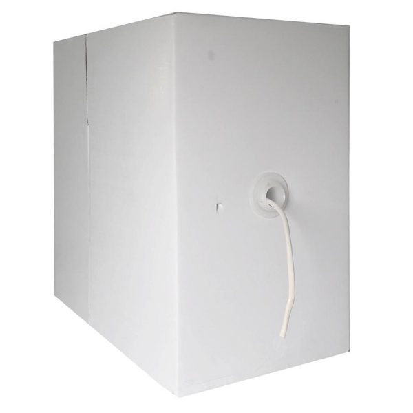
Related Products
[/vc_column_text][/vc_column][/vc_row][vc_row][vc_column]
Frequently Asked Questions (FAQ)
1. What is an Ethernet cable used for in security camera systems?
- Ethernet cables are used to transmit data and power (via PoE) between security cameras and network devices, such as NVRs or switches.
2. Do I need special tools to connect an Ethernet cable to a security camera?
- Yes, you will need a cable stripper, RJ45 connectors, and a crimping tool.
3. What is the standard wiring configuration for Ethernet cables?
- The standard wiring configuration is T568B: White/Orange, Orange, White/Green, Blue, White/Blue, Green, White/Brown, Brown.
4. Can Ethernet cables provide power to security cameras?
- Yes, if using Power over Ethernet (PoE), the Ethernet cable can transmit both data and power to the security camera.
5. How do I ensure a good connection?
- Use high-quality tools, ensure wires are properly aligned in the RJ45 connector, and crimp securely.
[/vc_column_text][vc_separator][/vc_column][/vc_row][/vc_section][vc_section][vc_row][vc_column][vc_column_text]
Any Questions? Contact Us Today
[/vc_column_text][/vc_column][/vc_row][vc_row][vc_column][contact-form-7 id=”9555″][/vc_column][/vc_row][/vc_section]
by