In this article we’re going to continue the overview of the newest menu system in TechPro Security Products DVRs (Digital Video Recorder) and NVRs (Network Video Recorder). The new system is set up to allow you to navigate the menu more easily through the use of links on most pages. If you have missed the previous articles in this 3 part series, you can read Part 1 of the DVR/NVR menu system here and Part 2 here.
In this article will be examining the features which are available through the bottom row of the main menu; the SETTINGS menu pages (see Picture 1). This portion of the menu system is very important because it’s going to allow you to configure how the DVR or NVR will be operating. This row of the menu has five main categories are Camera, Network, Event, Storage and System. This article will go over the first 2 (Camera and Network). Part 4 of this series will go over the remaining (Event, Storage, and System).
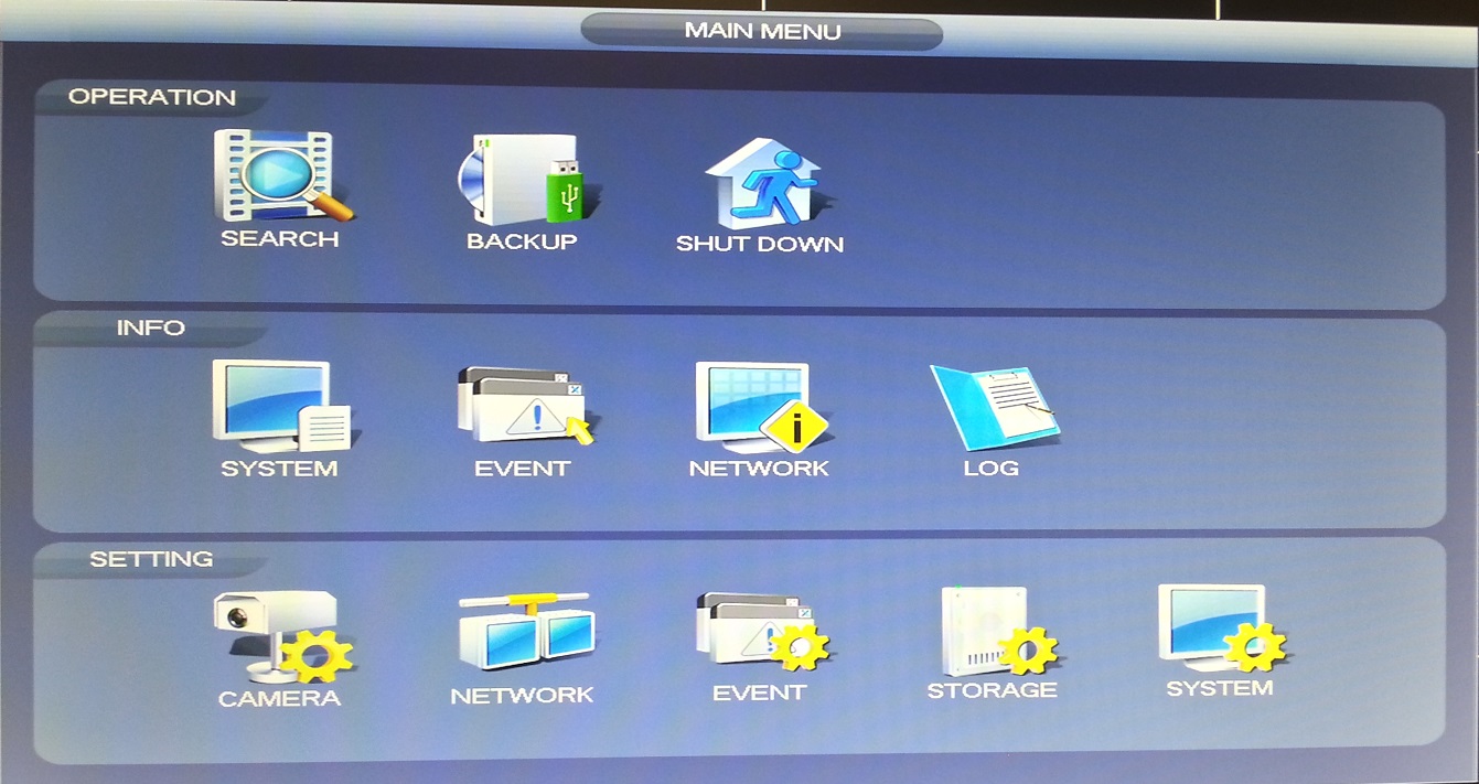
Picture 1
TechPro Security Products DVR and NVR Menu – Camera
This is the selection from the left side of the SETTINGS row of the main menu. Each of the other SETTINGS categories can easily be accessed through the links at the top of the page.
Image: (see Picture 2)
The settings on this page will allow you to affect the video in several ways for both live video and the way it’s recorded. These settings can be set up on a per camera basis and it can even be set up differently for different periods of the day. The way that most of these settings will affect the video differ slightly based on several variables such as lighting conditions and the range to the cameras target.
The more advanced settings are located at the bottom of this page. The previously mentioned variables are examples of some of the situations where these settings can be most beneficial. The ways that most of these settings can be helpful is fairly obvious although the bottom two options can use a little explanation.
The 2D NR and 3D NR both provide a digital noise reduction throughout the cameras view at different layers. The 2D noise reduction slider bar performs this function on 2 layers, while the 3D accomplishes this in 3 dimensions though out the entire image.
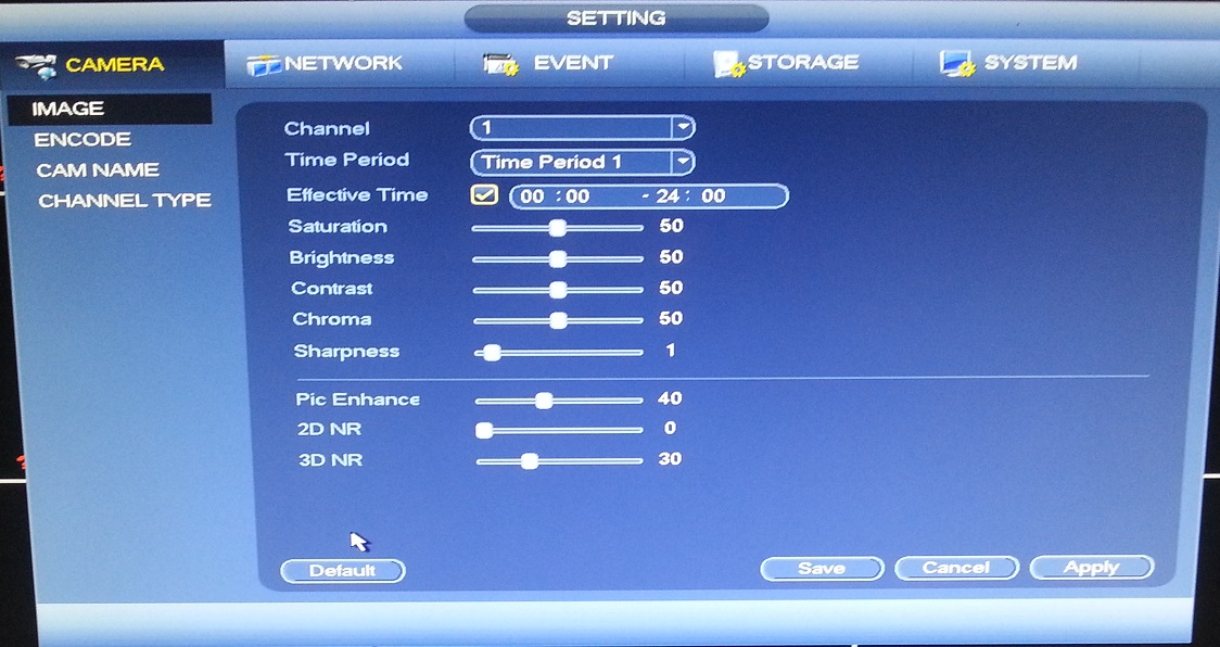
Picture 2
Encode: (see Picture 3.)
This menu page will allow you to configure the different video and audio streams that your DVR or NVR is processing. The settings for the main stream are located along the left side of this page. This column of settings is where you will set up the higher video quality for recording to any hard drives installed in the unit.
The column of settings along the right side of the page will allow you to set up the sub stream or extra stream for your desired purpose. This stream will use less bandwidth for data transmission because this stream uses lower resolutions. This stream is particularly useful when you’re remotely connecting to the recording device from a computer and/or mobile device, as it can help avoid latency issues.
The drop down menu labeled as ‘Type’ will give you the option of selecting Regular, MD (Motion Detection) or Alarm. These options will allow you to configure this page for each of these triggers for recording.
When you open the resolution drop down menu, you will see the highest resolution that is available on your DVR or NVR shown at the top of the list. The lowest resolution option will be shown at the bottom of the menu.
The Bit Rate is where you can set the speed of the data transmission from your cameras.
The Audio/Video check boxes enable those types of signals for the main stream, extra stream or both.
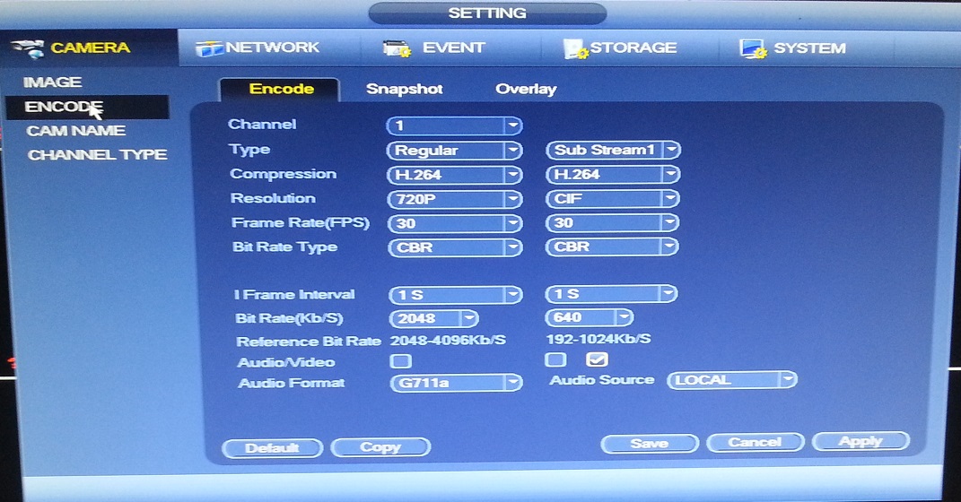
Picture 3
Cam Name: (see Picture 4.):
This menu page is where you can set the name for each channel. This will be displayed in the corner of each camera’s view.
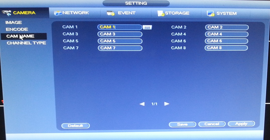
Picture 4
Channel Type: (see Picture 5.)
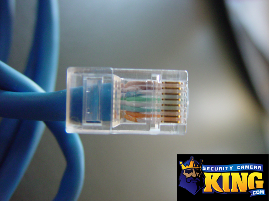
This page will allow you to select what type of camera or cabling will be used for connecting a camera to each channel. This page is not available on all models of DVRs or NVRs.
Coax – This should only be selected if you’re using RG-59 or RG-6 to transfer the video from the camera to the DVR.
UTP – This option should only be selected if you’re using Ethernet cable with baluns designed specifically for use with HD-CVI cameras
IP – This option should be selected if you’re using IP cameras on this channel.
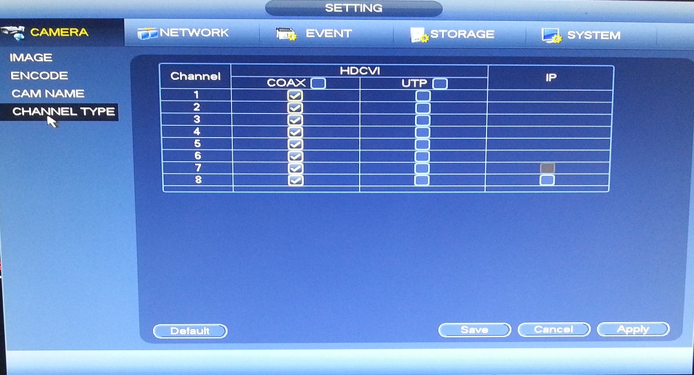
Picture 5
TechPro Security Products DVR and NVR Menu – Network
This section of the menu system will allow to customize the way that your DVR or NVR interact with the network where it’s connected.
TCP/IP: (see Picture 6.)
You will need to enter your network’s Default gateway here, as well as a unique IP address based on that IP scheme. For example, if your default gateway is 192.168.1.1 then 192.168.1.25 would be a viable IP address as long as it’s not in use by another device on your network. Most of the rest of the info here will stay the same as the default settings.
This page will also list the MAC address of the recording device.
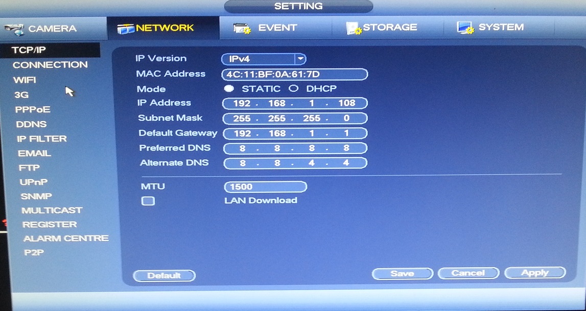
Picture 6
Connection: (see Picture 7.)
This menu page shows the ports that are currently being used by your DVR or NVR in order to establish a connection with a remote device. The only port that is usually changed is the HTTP port. It is most commonly changed to 88. The HTTP port and the TCP port need to be forwarded through your network’s firewall before you can remotely connect to your recording device from outside the network where it’s located. The most common reason for our customers to contact our tech support team is for assistance with this process.
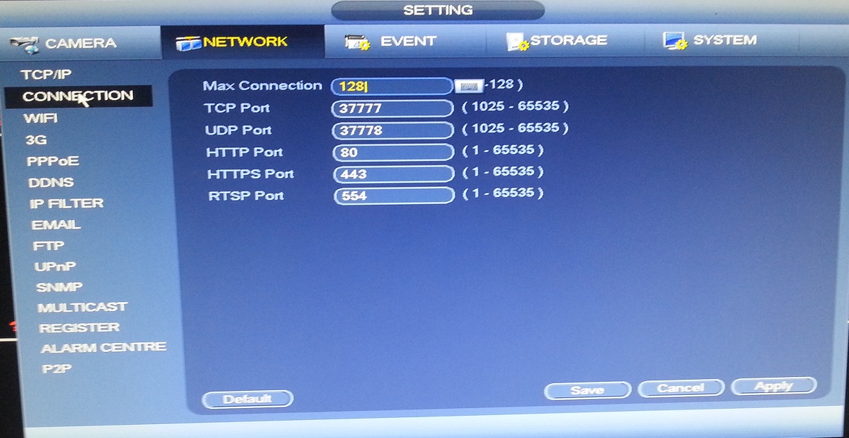
Picture 7
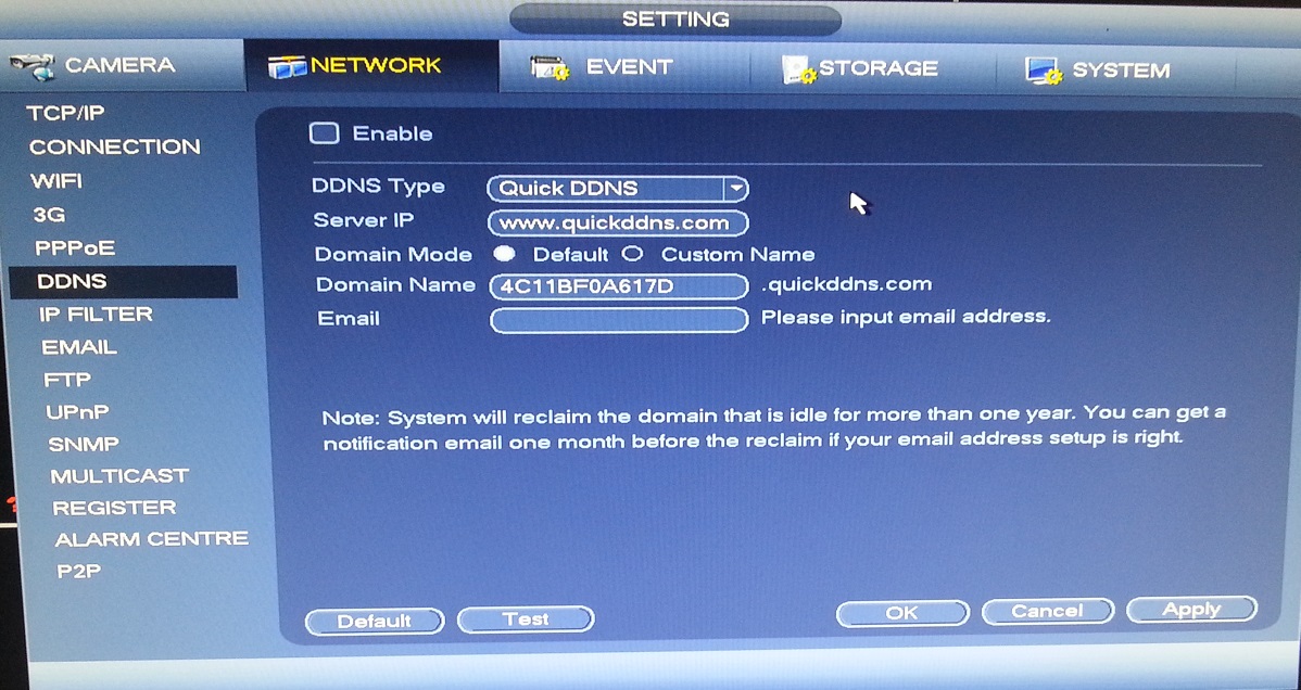
DDNS: (see Picture 8.)
This menu page will allow you to configure your DVR or NVR to work with a DDNS service.
By default, most external IP addresses are dynamic. This means that the IP address can change for a variety of reasons and it will not be possible to connect remotely until you find out the new IP address. A DDNS account can eliminate this problem.
Picture 8
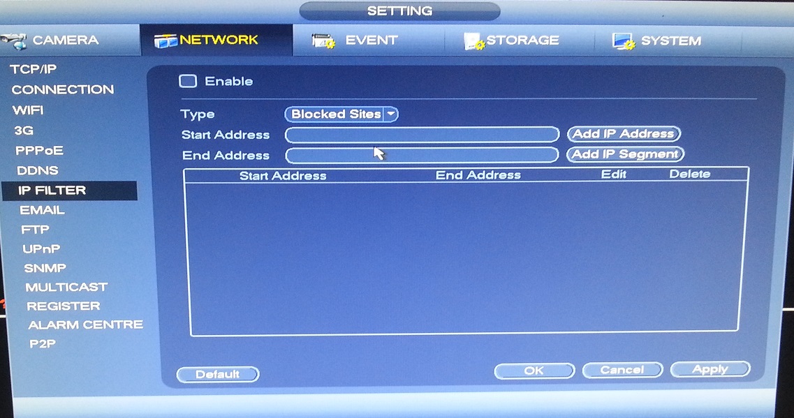
IP Filter: (see Picture 9.)
This menu page will allow you to block specified IP address from remotely connecting to your DVR or NVR.
Picture 9
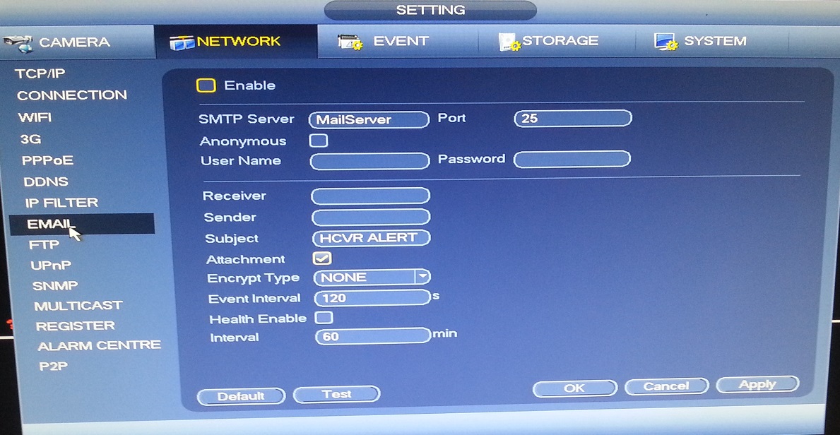
Email: (see Picture 10.)
This menu page is where you can configure the recording device to work with an email address. If you have any issues with the set up then you should contact our tech support department.
Picture 10
Stay tuned for Part 4 of this series that will finish up the rest of the menu settings. If you wish, click the box below to be notified of new posts on this blog.