

Many of you are asking how to access a Recorder directly without the use of a Router, this can be confusing and frustrating at times where the customer has no router and you do not have a monitor.
The solution is simple. You can create what is called a “router to router crossover cable”. Many market this cable as an “RJ45 crossover cable”. We will be utilizing that Market term in this Article. This will allow the use of a computer as a “Monitor”.
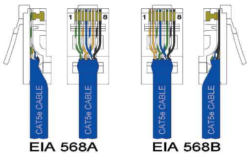
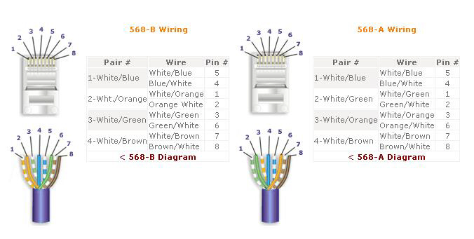
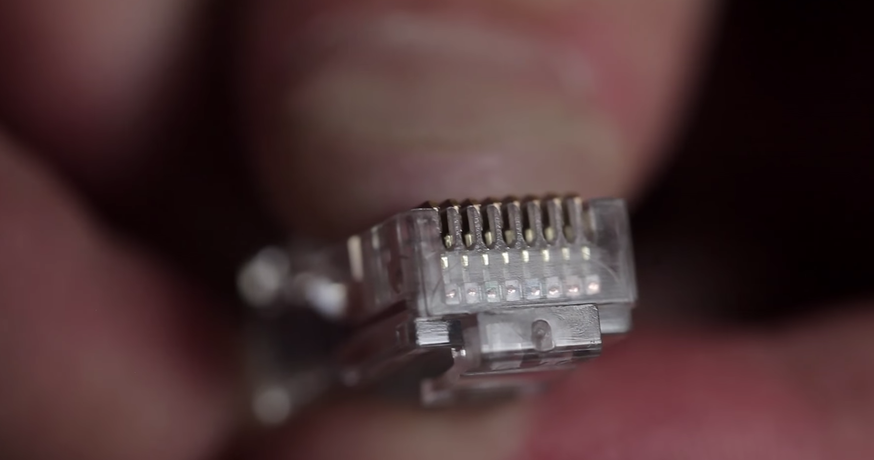
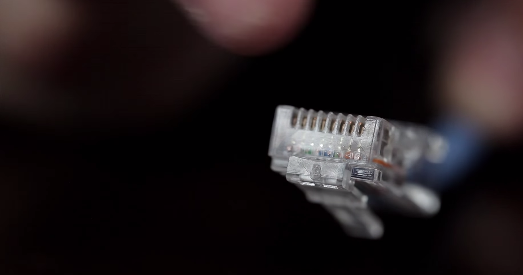
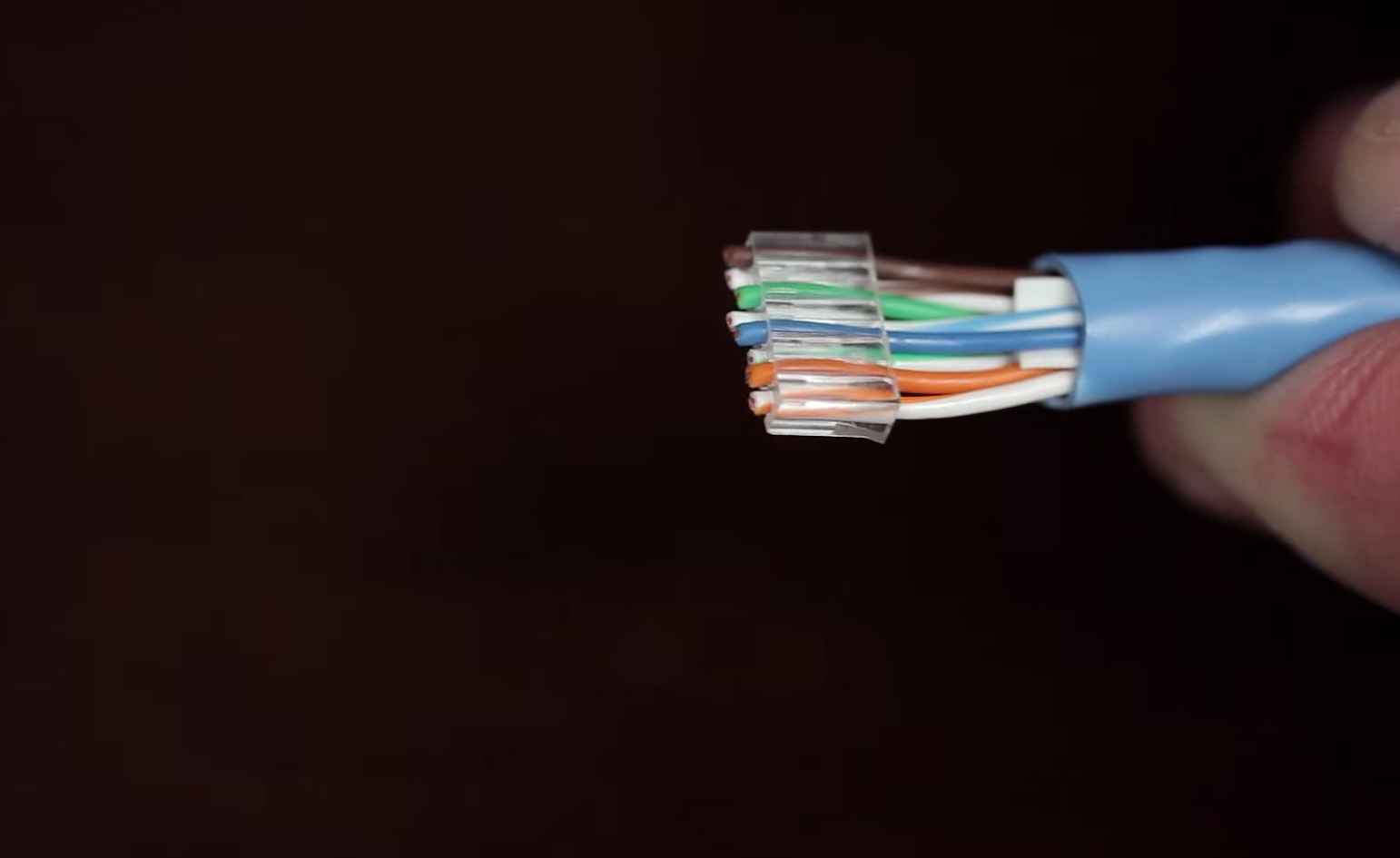
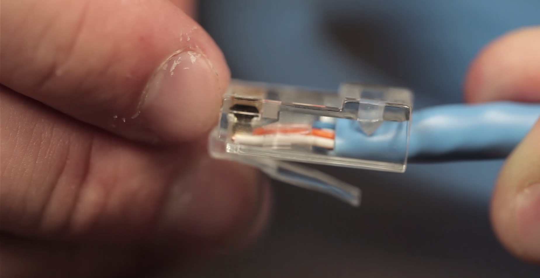
We first need to understand what an Ethernet cable is composed of. An Ethernet cable has 4 pairs of wires all color coded. You can attach the RJ45 Connectors to the cables either using standard A or B color codes. A standard cable would either be A+A or B+B on each ends using RJ45 Connectors.
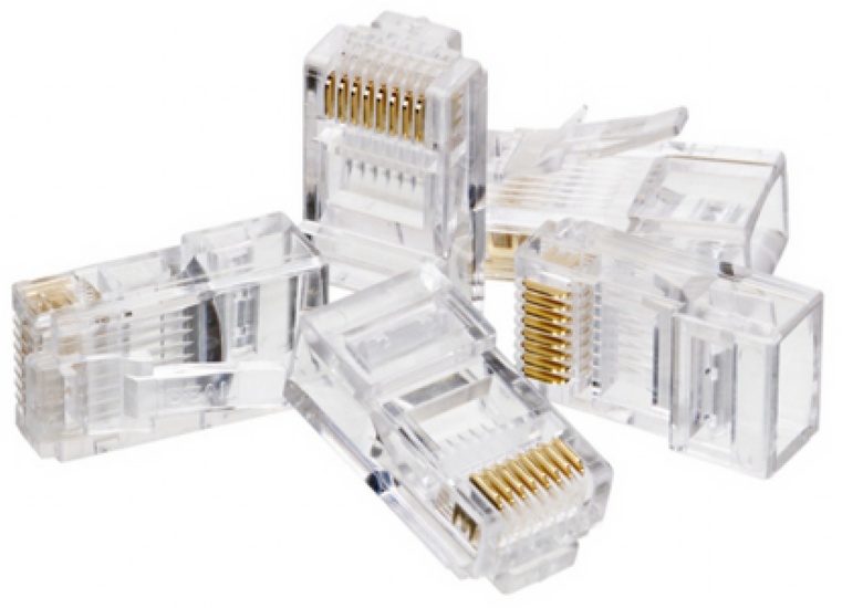
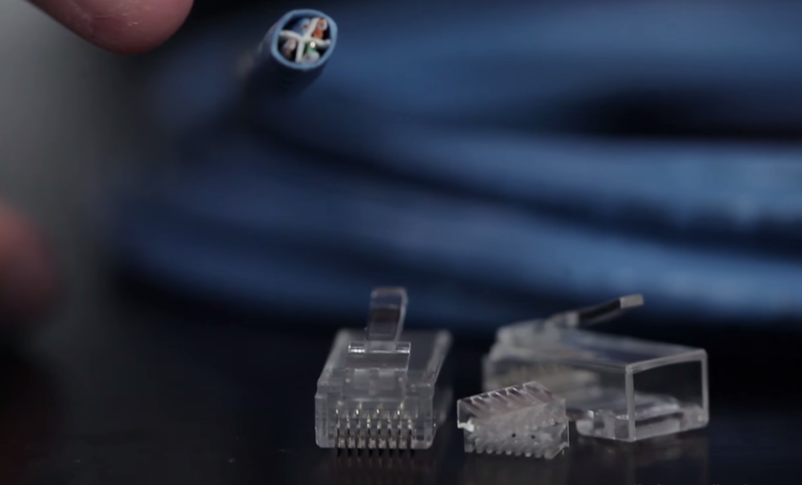
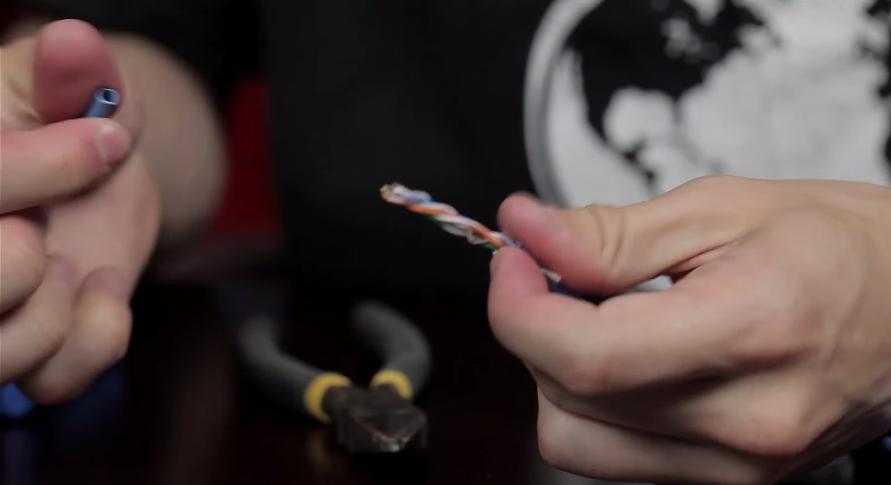
You can grab any old Ethernet cable to create your cross over cable or a new cable. Get yourself a pair of RJ45 connectors
Using Cat5 Cable
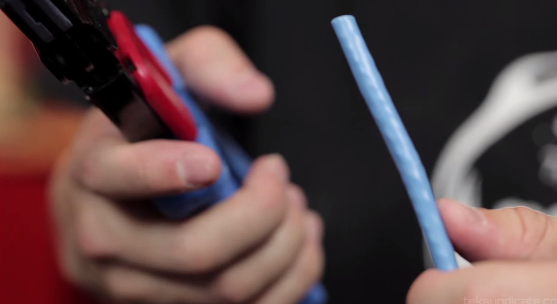
Cut the Outer Insulation with your Crimp tool using the knife .
Strip your Category 5 Cable
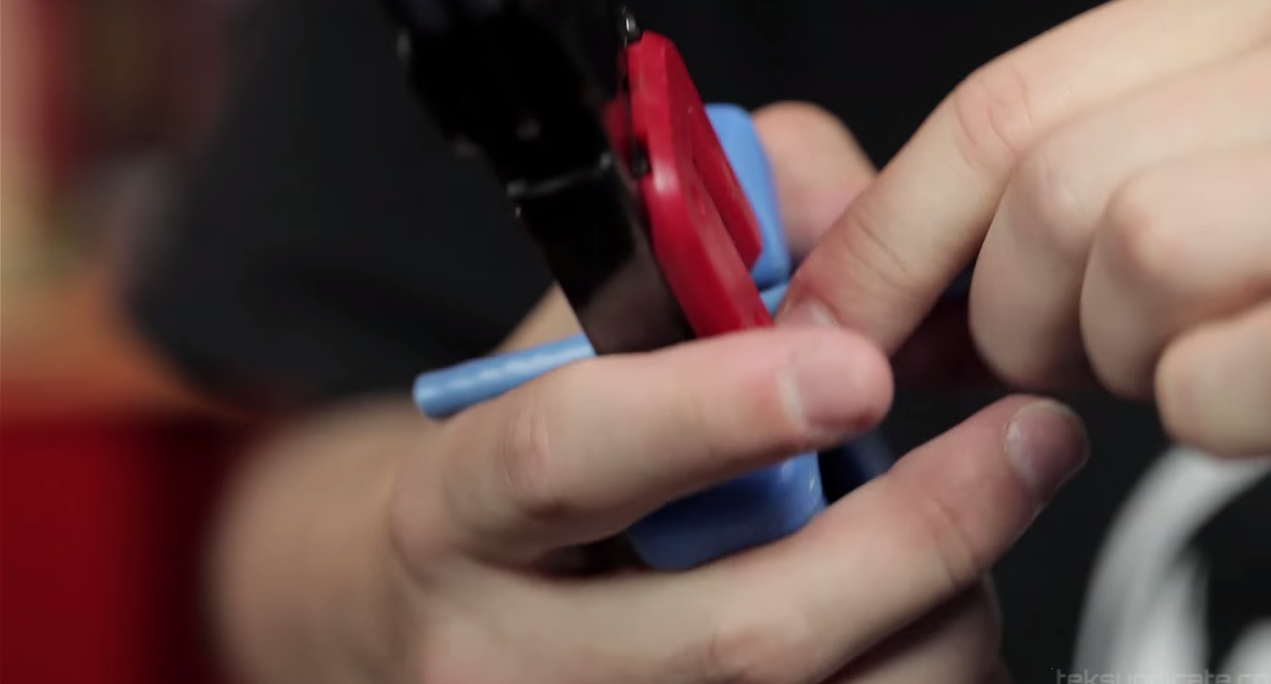
Remove the insulation
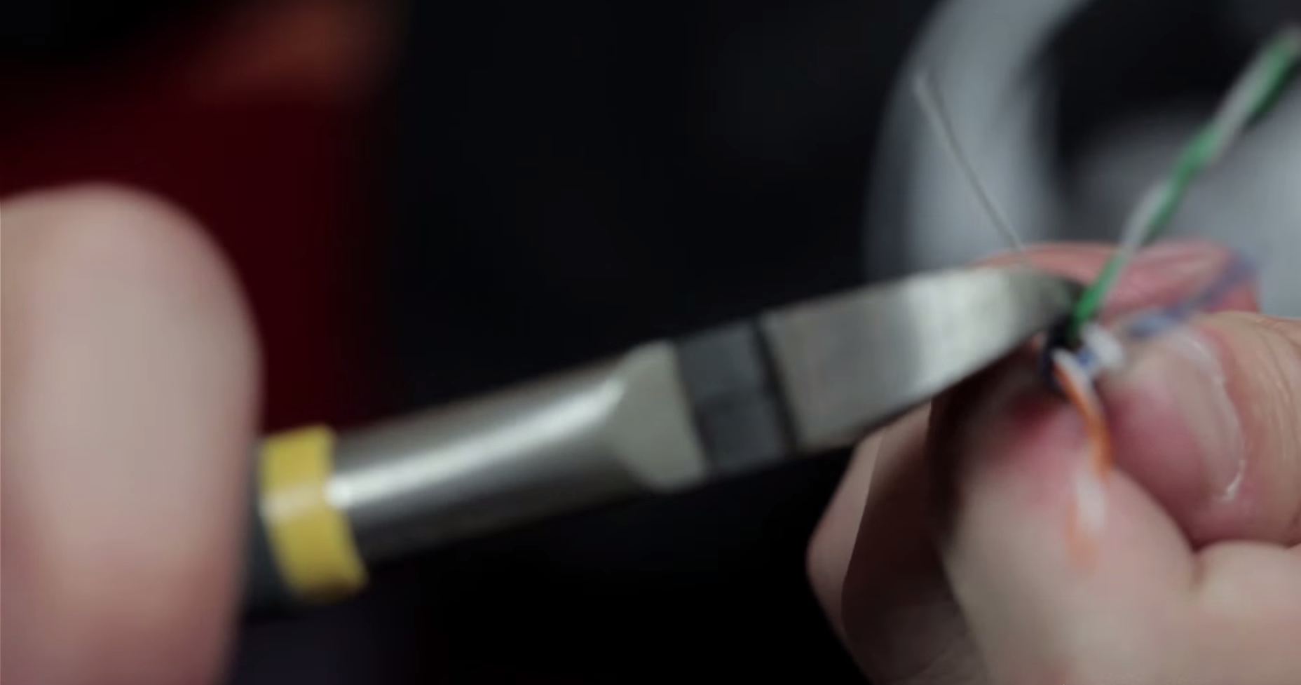
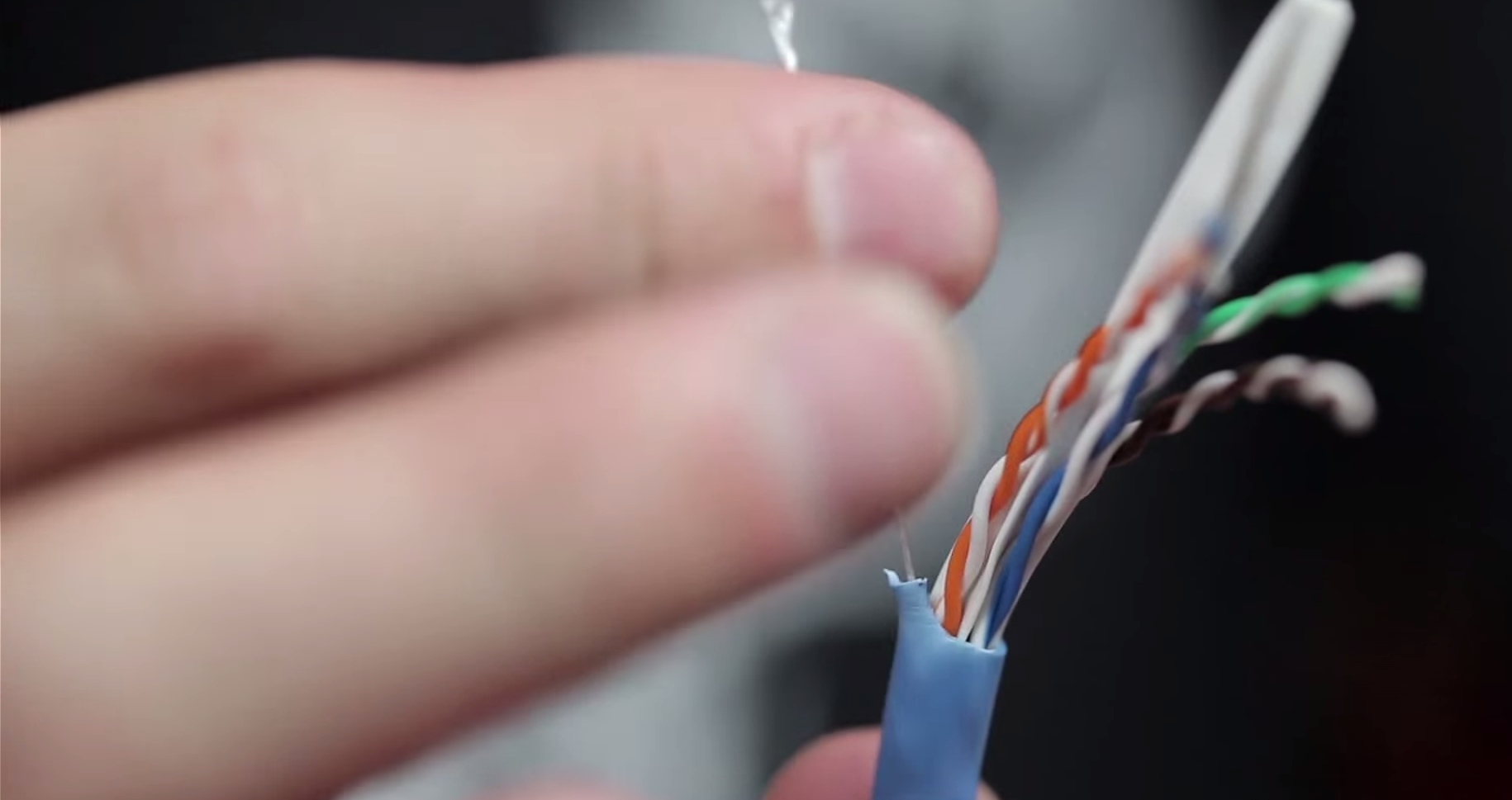
Find the String which is used to expose extra wires and cut it
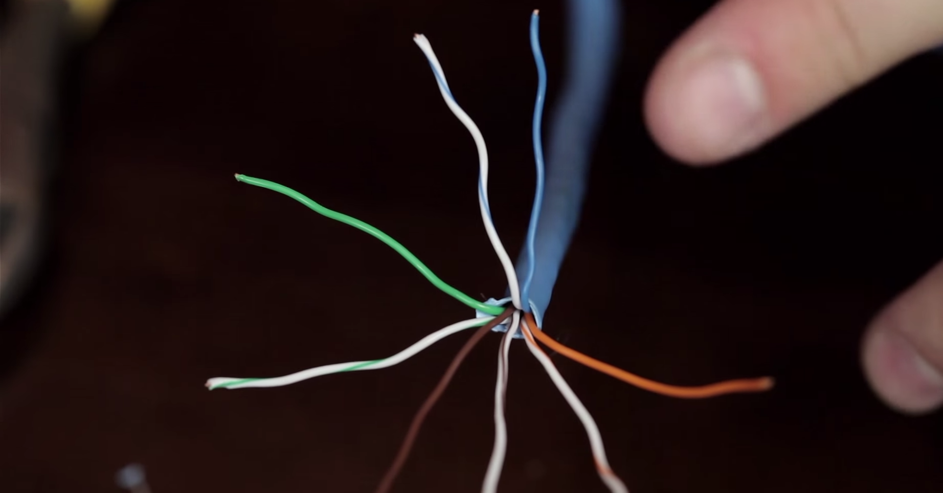
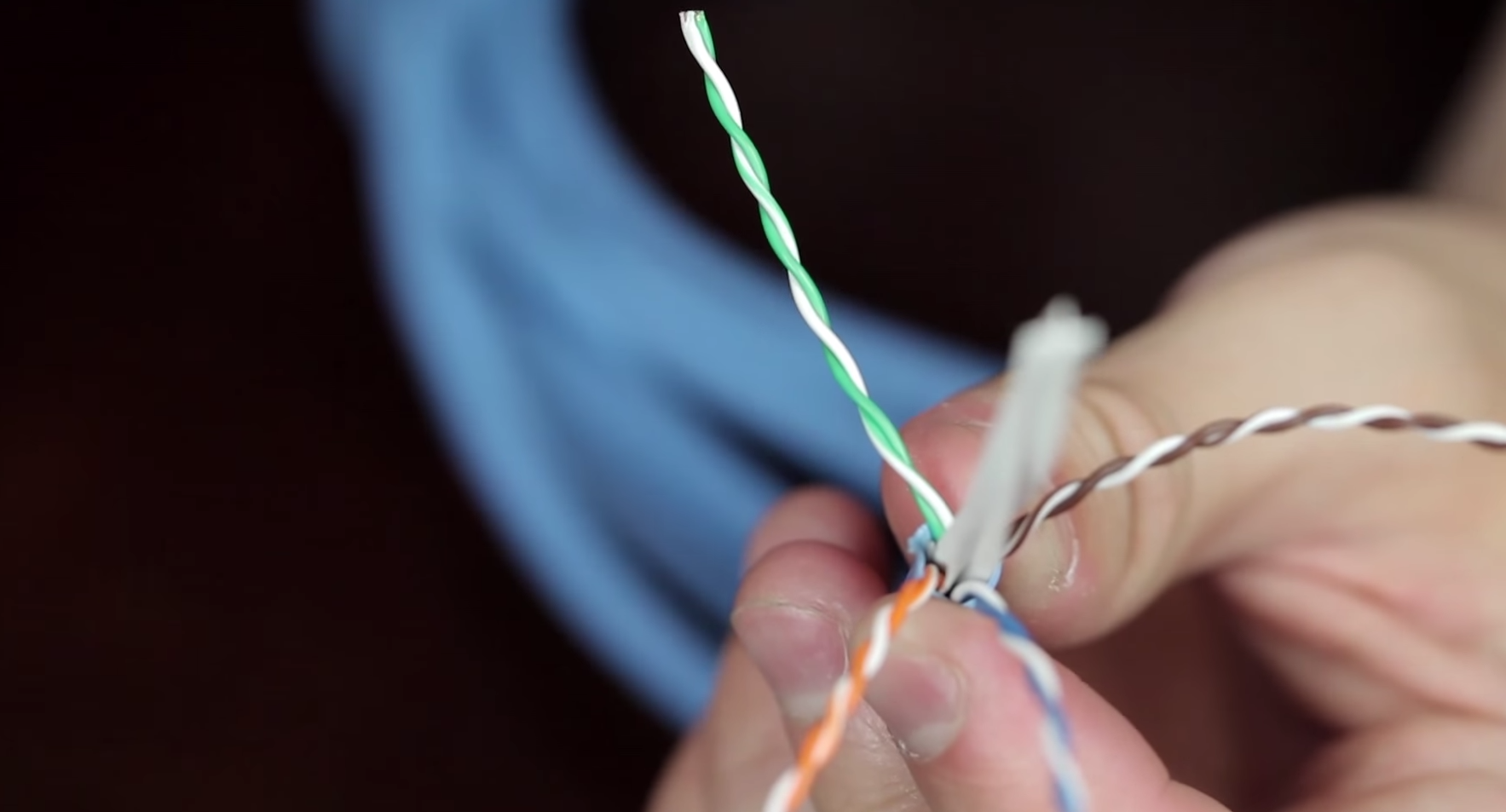
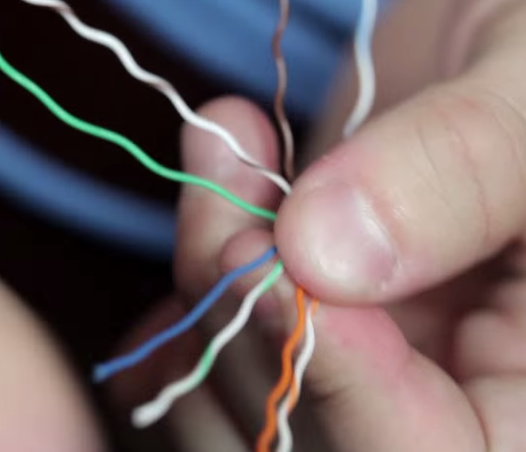
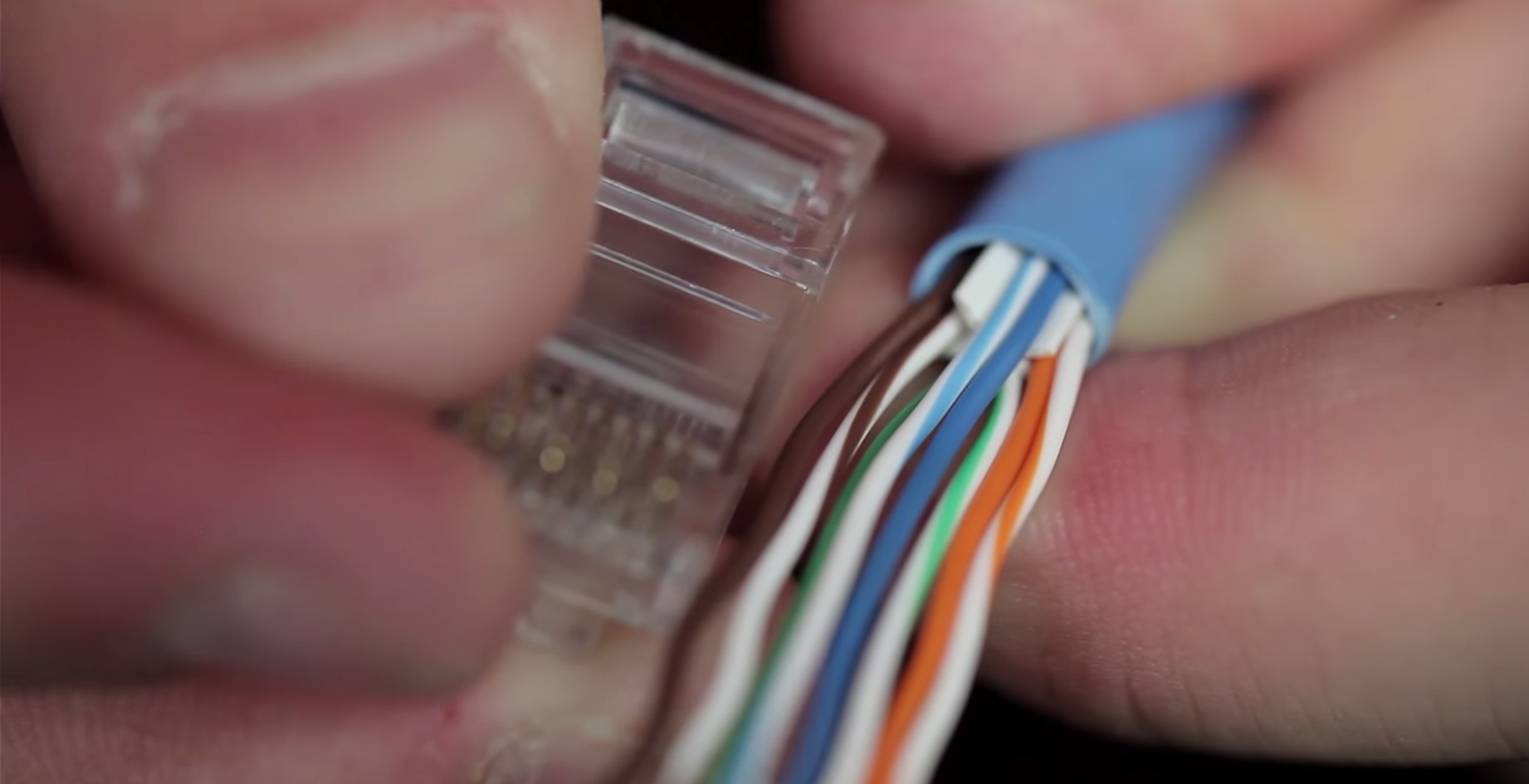
Separate the conductors
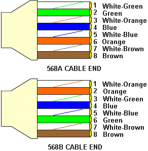
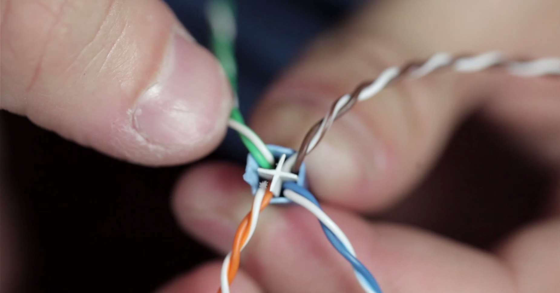
Match your color codes
Make one end to match the 568-A and the other end to match the 568-B
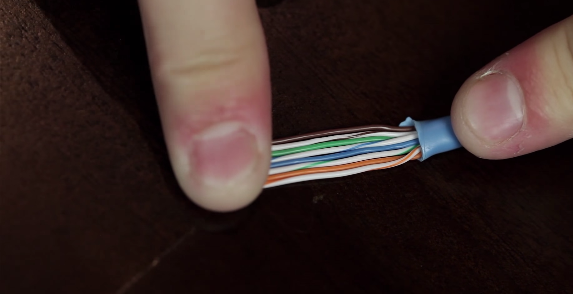
 Measure the length that you would require
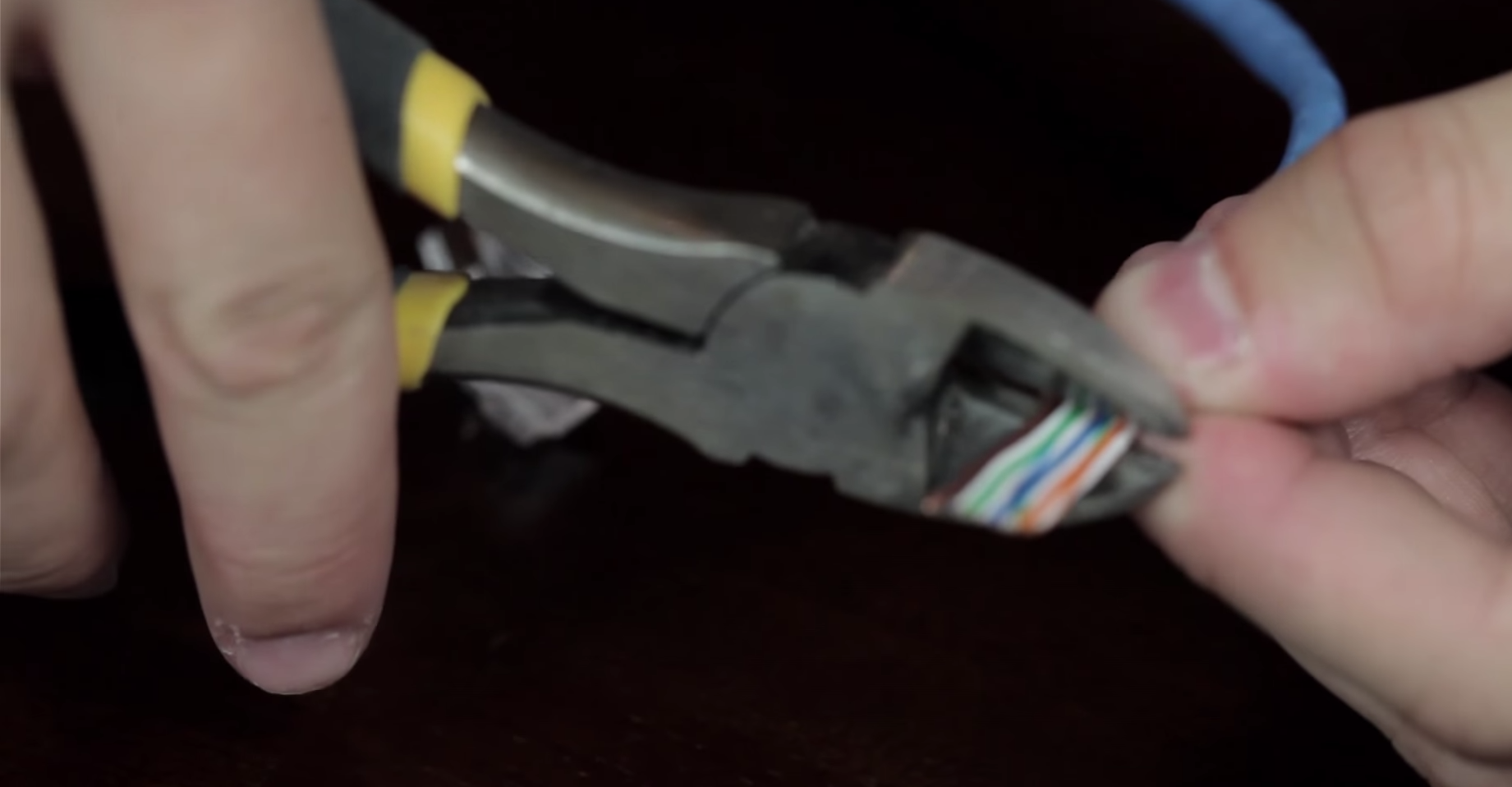
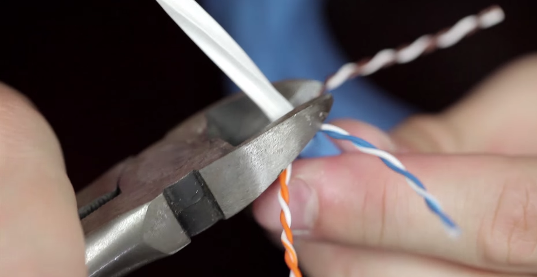
Cut the conductors making sure the you are not cutting at an angle
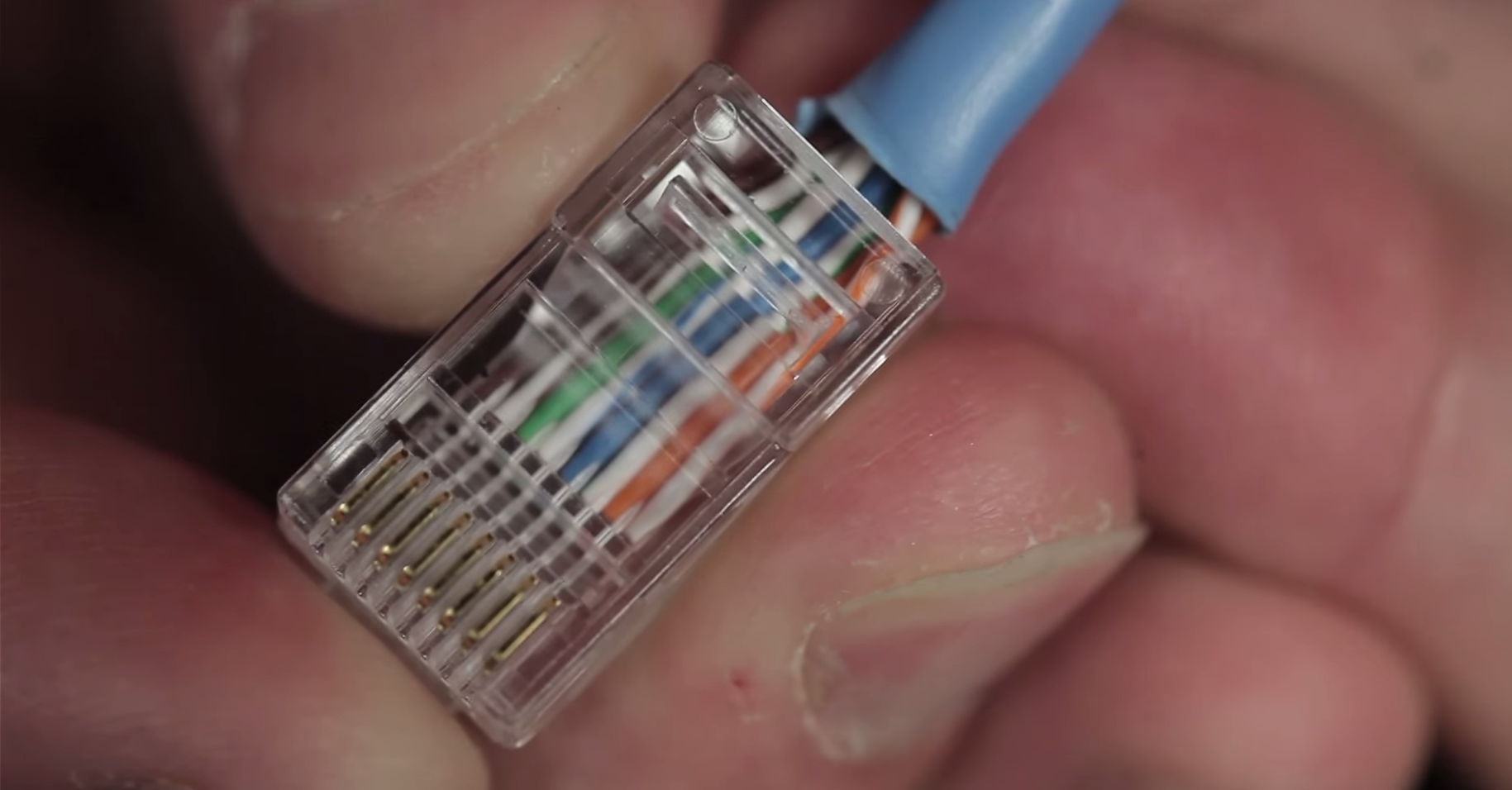
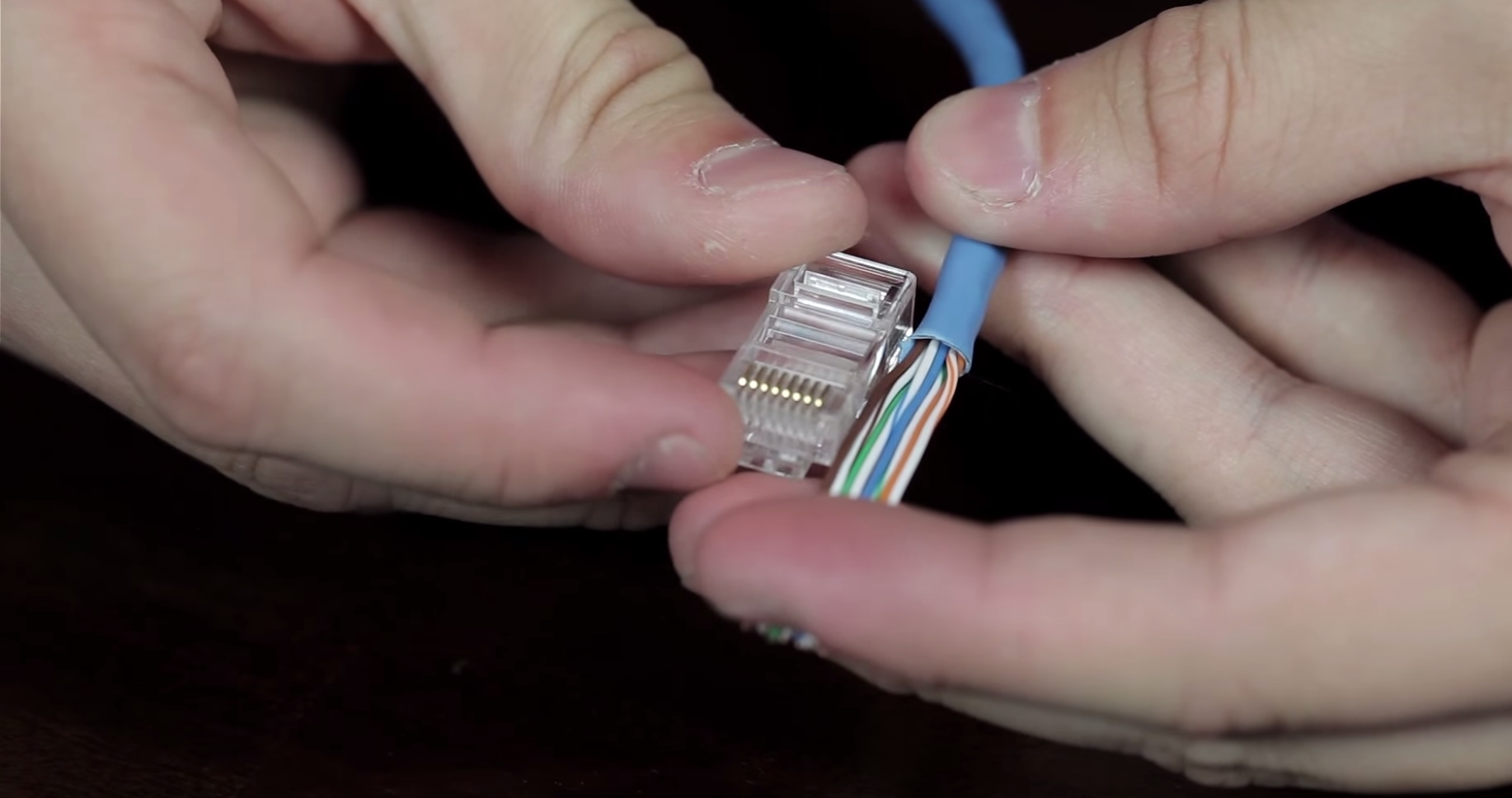
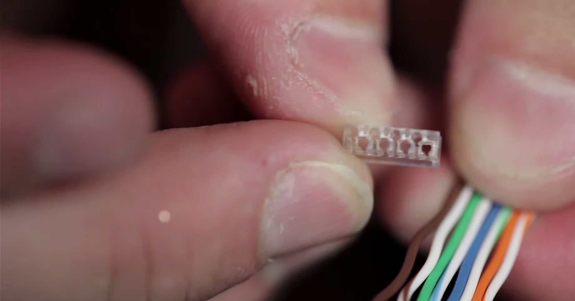
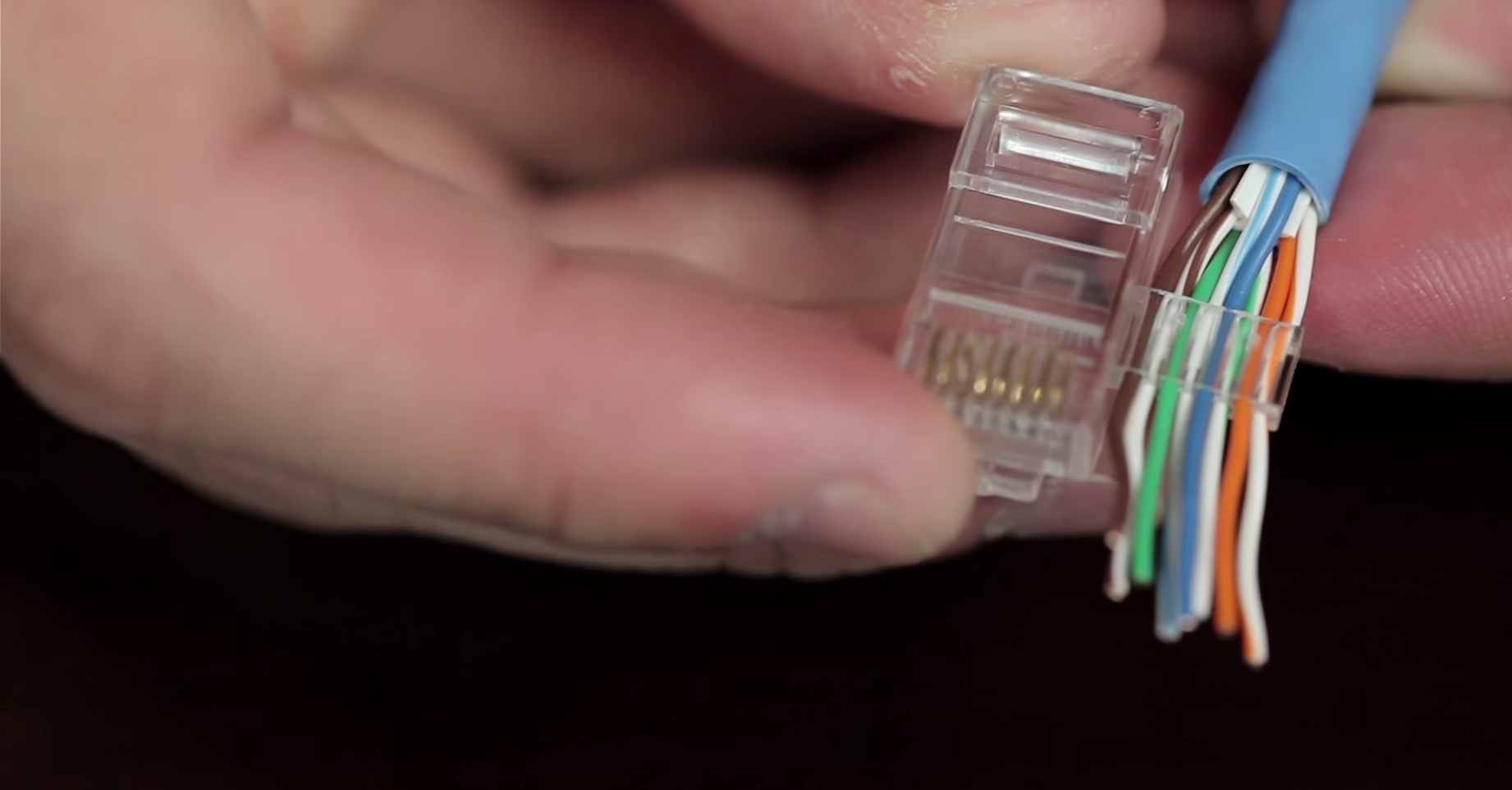
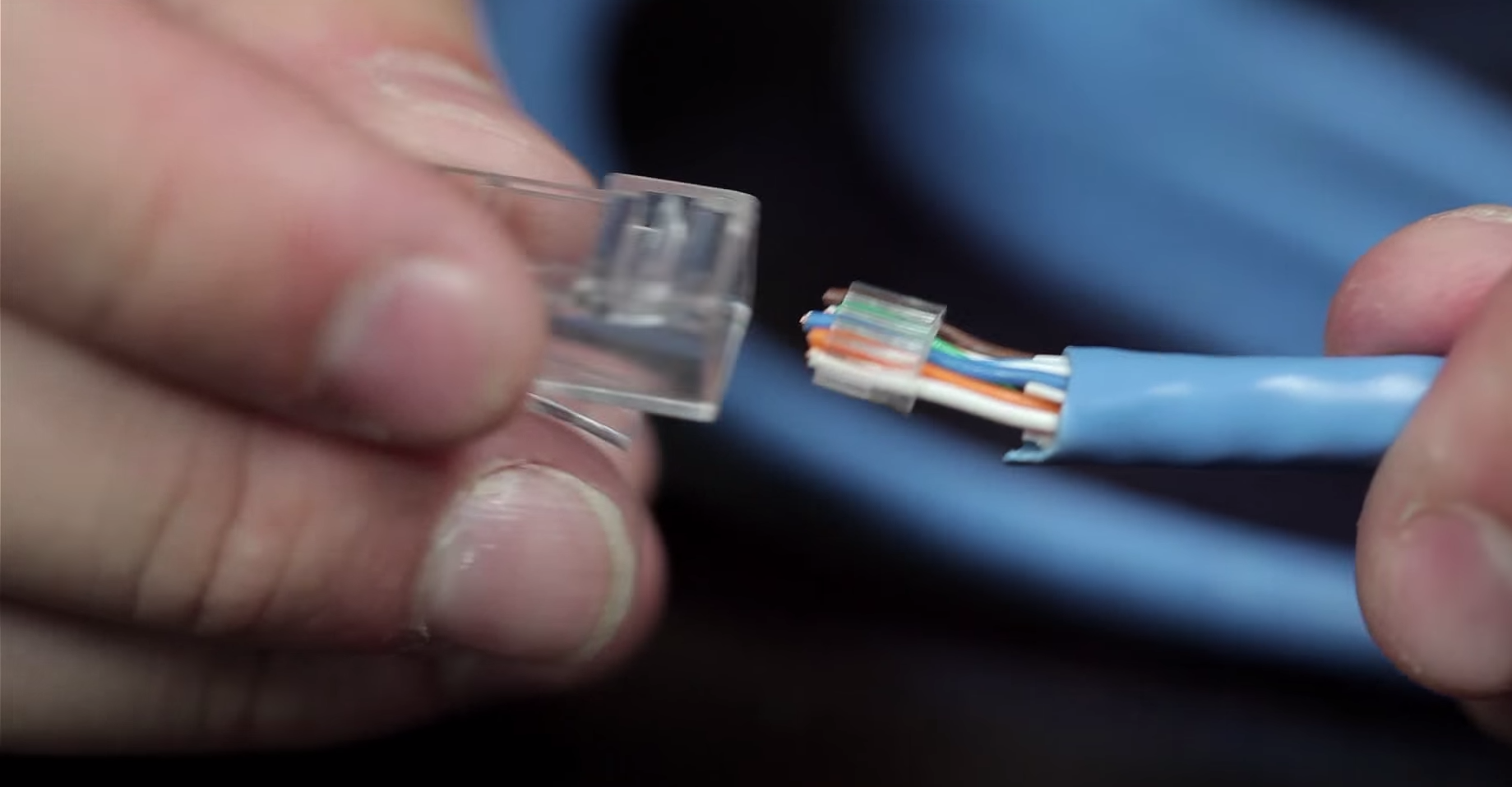
Add the connector on each end. Making sure that the conductors are on the proper channels
Double check your work before crimping the connector.
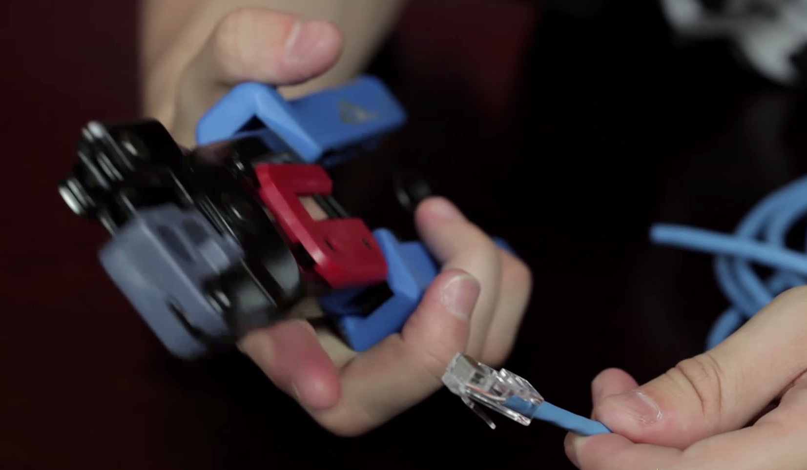
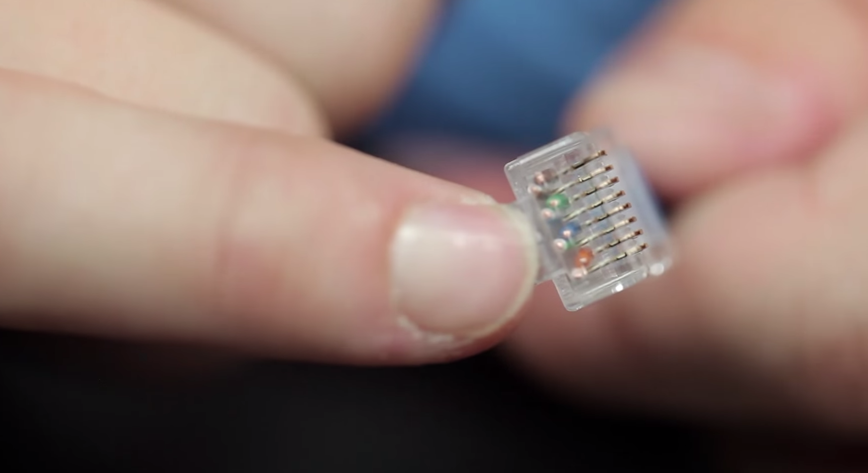
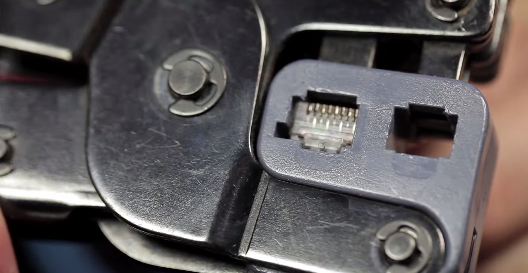
Use your Crimp tool make sure that the RJ45 connector is seated properly
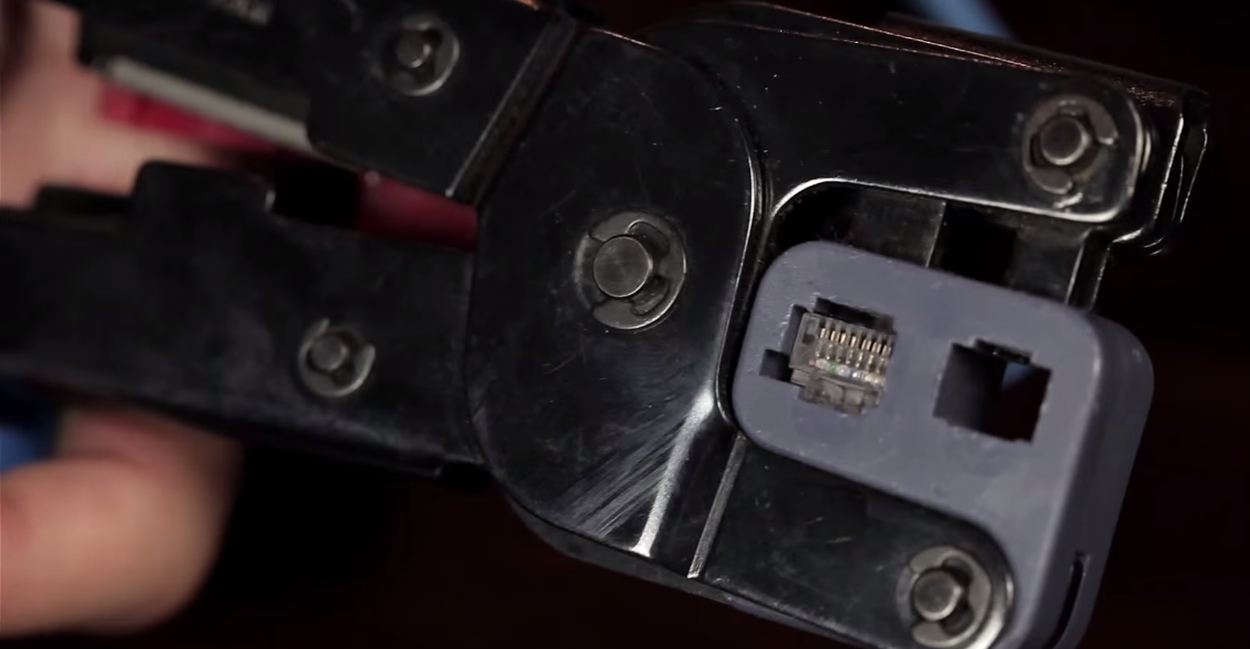
Crimp! crimp! crimp!
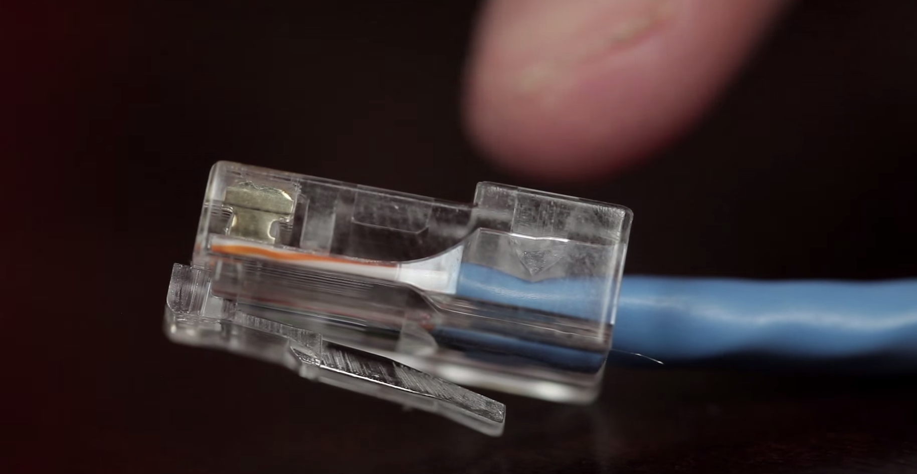
Final Product!
Using CAT6 Cable
Get your Cat6 Cable and Crimp Tool
Cut using the tool to remove the outer shielding
Remove the string by pulling at it while cutting this will hide the string inside.
Separate your conductors. Good info to know is that cat5 cable is 24 gauge conductors and cat6 is 22 gauge wires.
Cut the Middle insulation separating spline if you will.
Pro tip: Pull on the insulation and cut. This will stretch the material enough for you to cut and once you cut it will go deeper inside.
Make sure if you have not cut into any of the conductor’s insulation. If so start over again. The reason is you will have more noise coming out of the conductor which will degrade the signal .
Separate your conductors
Measure the length of wires you would require
This piece here comes with this type of connector it is best to use this type for cat6 cable. This will help with insulating the conductors from cross-talk. Cross-talk is produced when electricity is flowing through the wires. This is why cat6 has all the extra insulation and has less cross-talk than cat5 cable.
Measure again before cutting the conductors
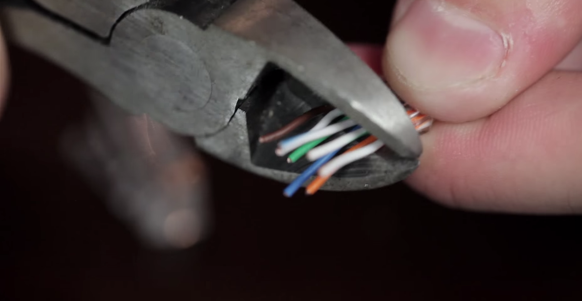
Make sure the pliers or cutters are not in an angle when cutting
Connect the cable to the RJ45 connector
Final Product! 😉
After you have completed the process of making your Cross Over cable some networking changes need to be done on your computer.
Macintosh Computer
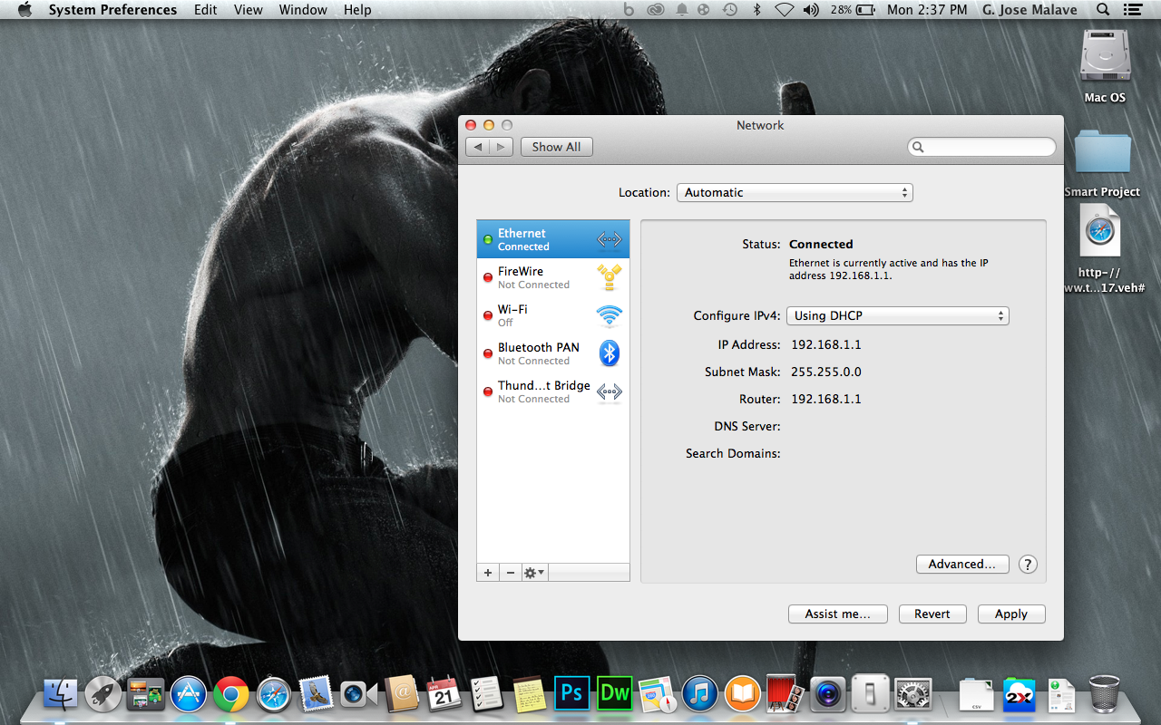
Navigate to the System Preferences and go to the Network tab. Here you will see the Network settings we will be focusing on the “Ethernet” option. Make sure that your WiFi card is turned off.
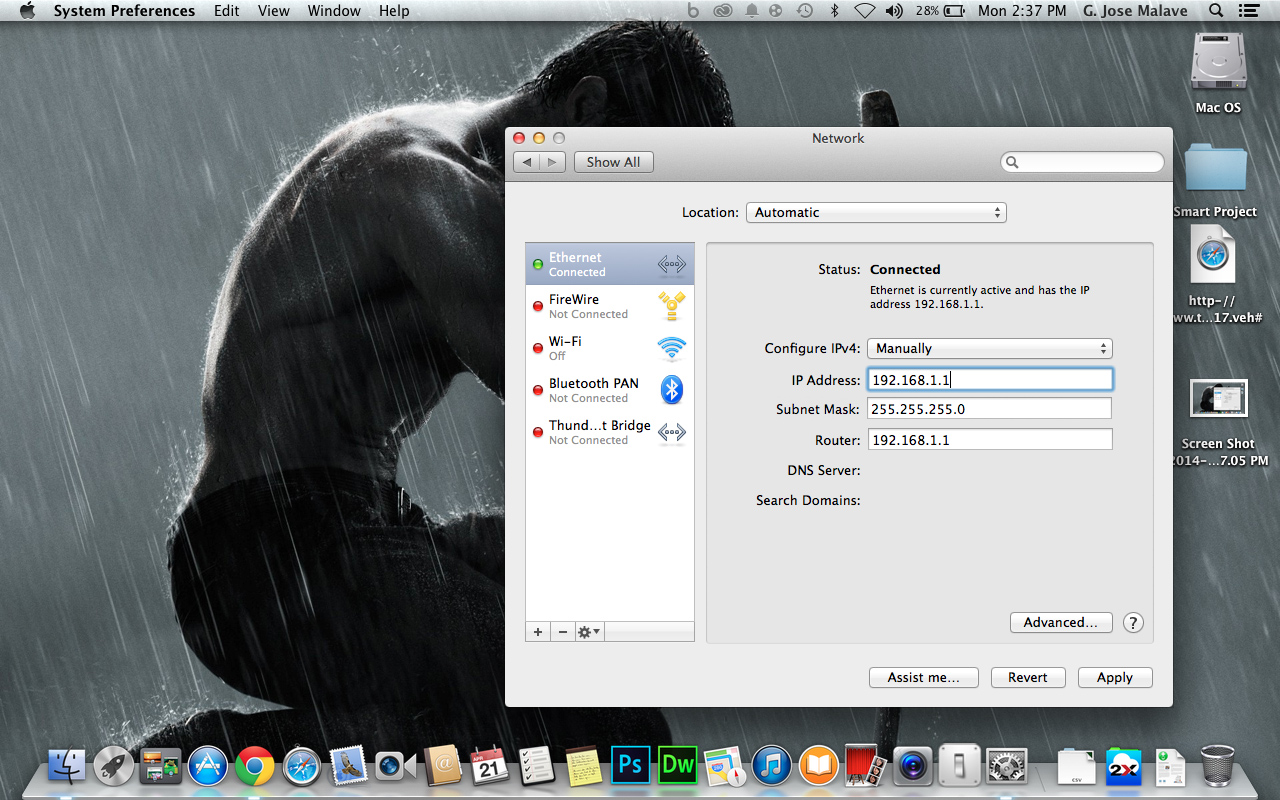
Adjust your Settings to “Manually”
Set your IP address to 192.168.1.1
Subnet Mask to 255.255.255.0
Router: “Gateway” should be 192.168.1.1 as well
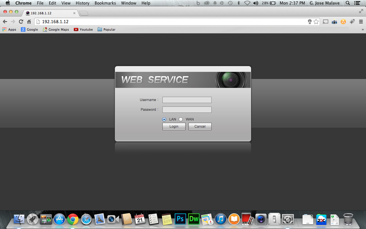
Here is an image of a successful connection on a MacBook Pro.
Note that not all recorders will allow you to access them via a browser using a Macintosh however you can directly manage an IP camera.
You can of course use the PSS Software or Smart PSS for viewing purposes on your Mac.

In this case this recorder had already been assigned an IP of 192.168.1.12 If you did not know your Recorders IP try 192.168.1.108 or use the IP Scanner Application to search the Recorders IP.
Windows Computer
Navigate to your Control Panel, In my case I have Windows 8 so I have to go to Control Panel/All Control Panel Items/Network and Sharing Center. This will be the same for Windows 7
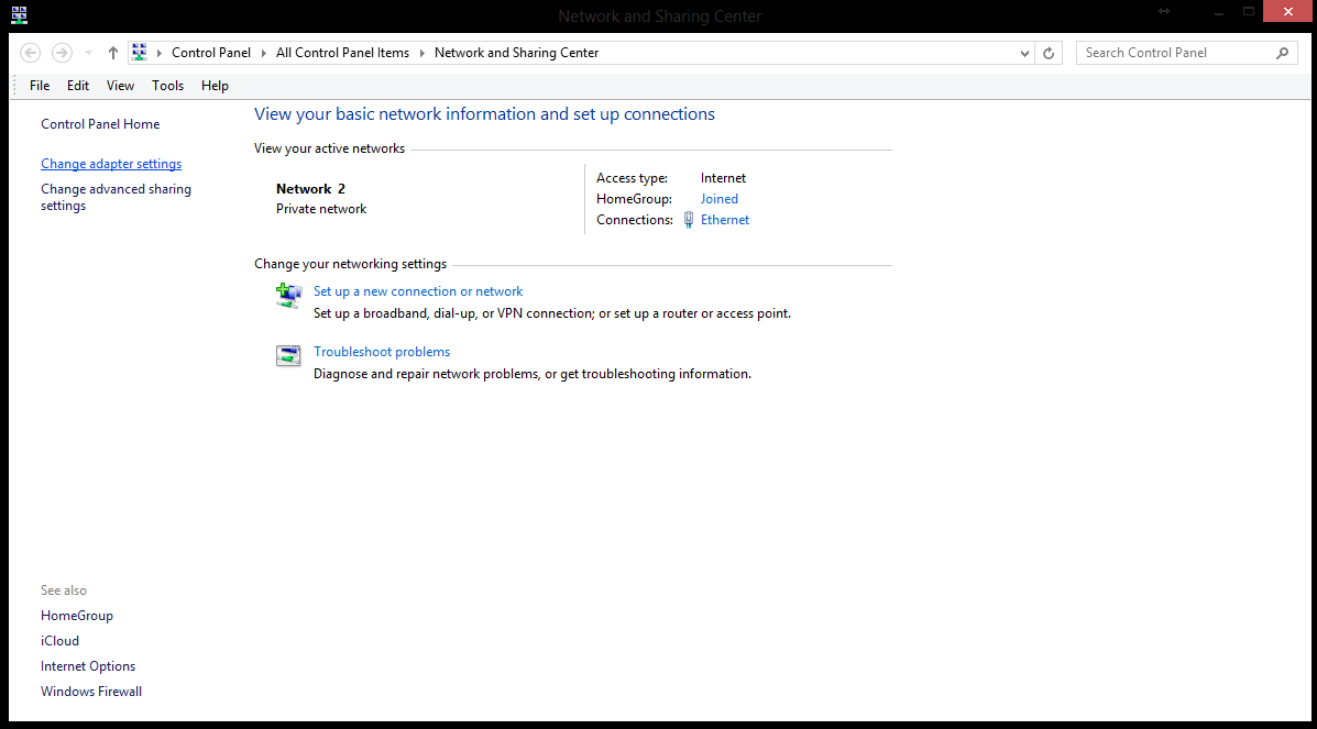
Once you are here click on Change adapter settings. This will open all of your Network adapters if you have a WiFi card on your computer you should disable it or simply disconnect from any Access Points that you might be on in my case I chose to disable it.
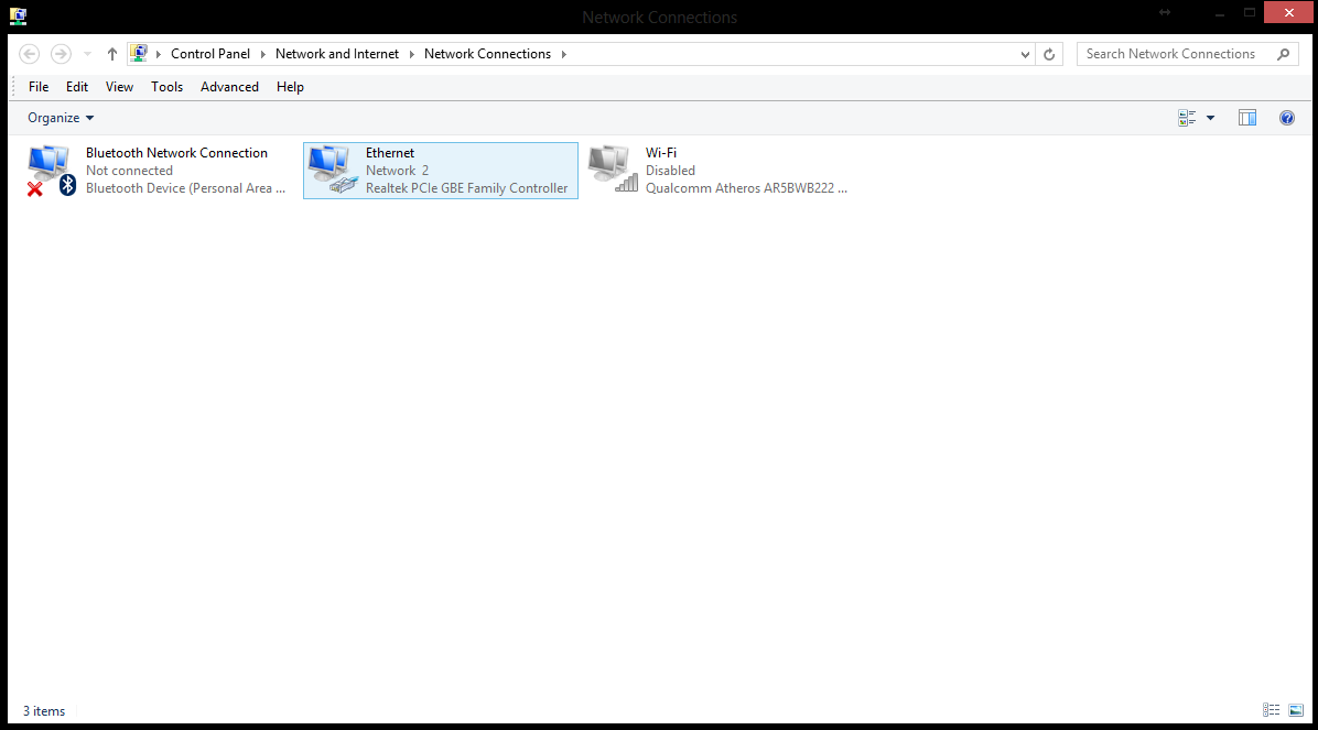
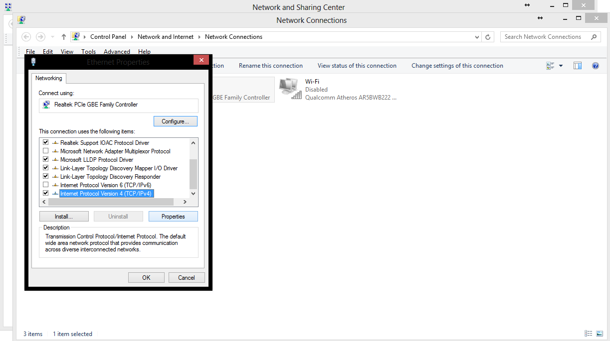
Right Click and choose Properties
This will open up a window. In this window navigate to Internet Protocol Version 4 (TCP/IPv4)
Match the settings bellow.
IP Address should read 192.168.1.1 as well as the gateway and sub net should be 255.255.255.0
Use any DNS Server in my case i used Google’s DNS server . 192.168.1.1 should work as well
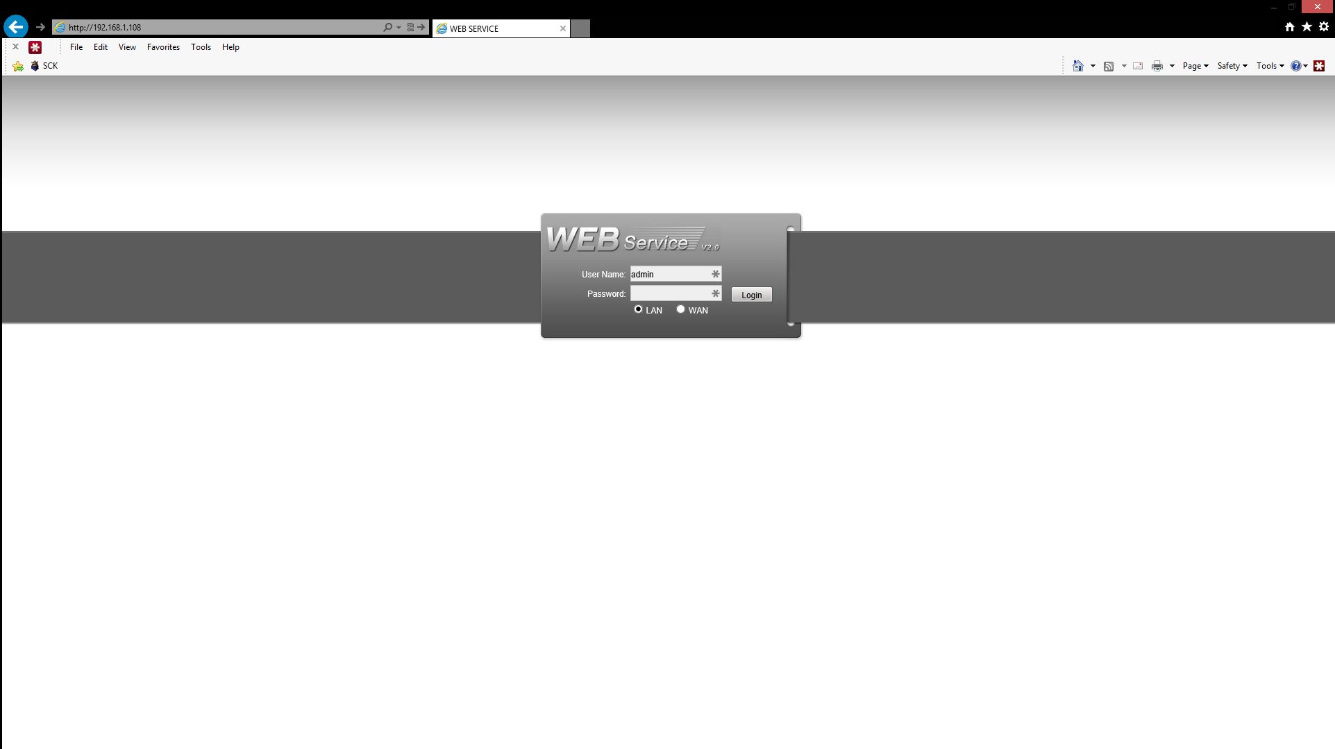
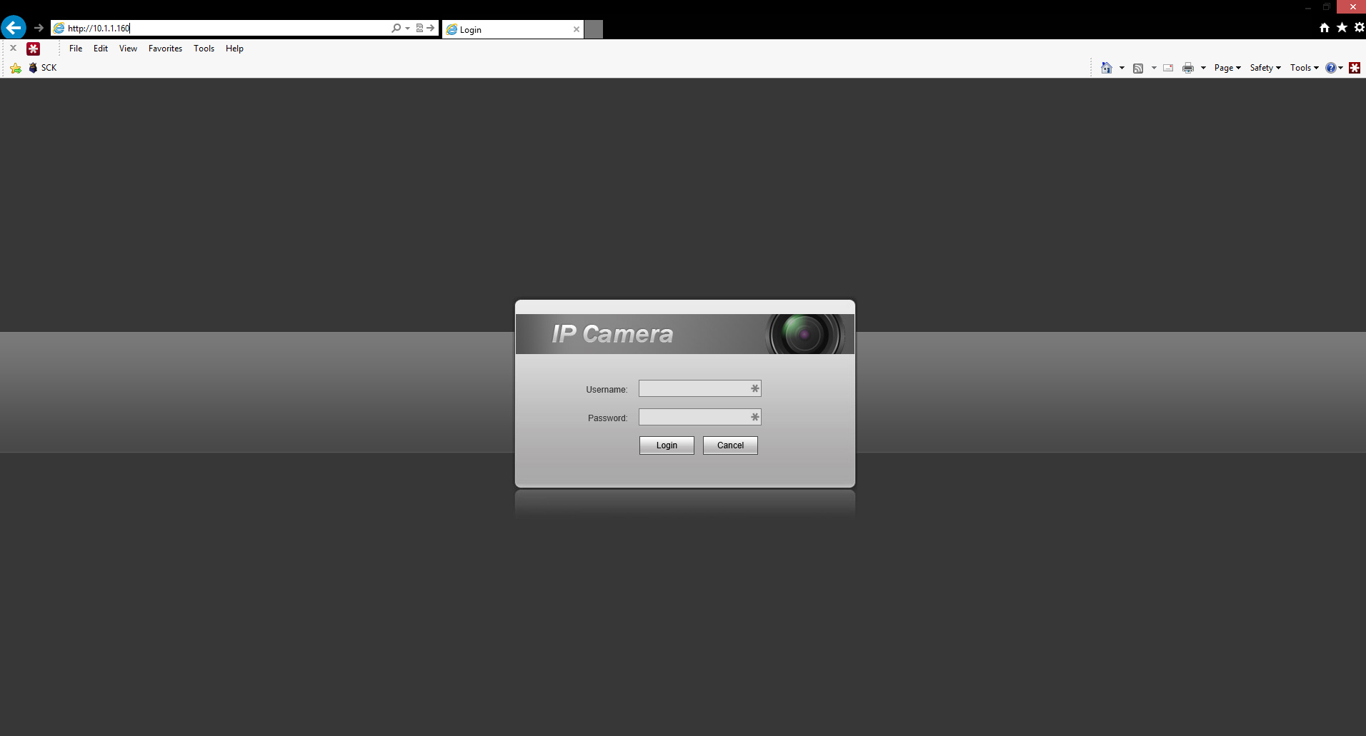
Once you have done this connect the Crossover Cable to the Recorder NIC card and the other side to the computer you will be using to configure it. Open your Internet Explorer Browser
Accessing an IP camera that is connected to the PoE switch of an NVR
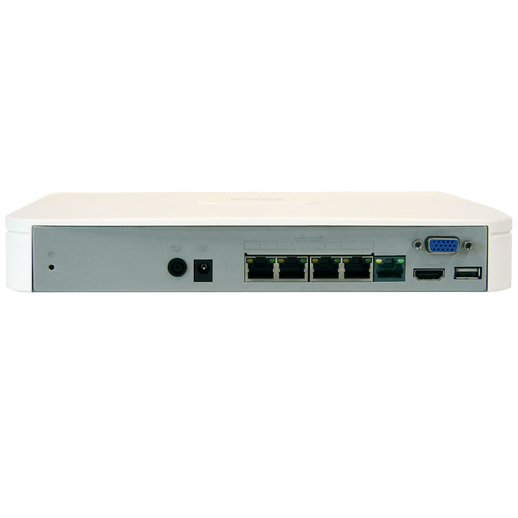
Simply connect a normal Ethernet cable to one of the ports of the PoE switch on the NVR
Wait to until your device is assigned an IP address.
You can use a IP Scanner tool (Angry IP Scanner – Windows)

The image above is used as an example you need to match the IP Scheme for instance my NVR’s PoE switch scheme is 10.1.1.1
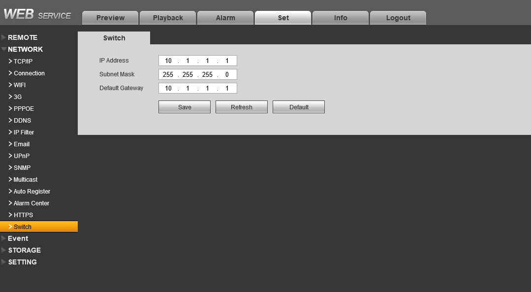
So I searched 10.1.1.1 – 10.1.1.255. The tool will give you the devices connected to the PoE switch.
(IP Scanner – Mac) to scan and see what the cameras IP are .
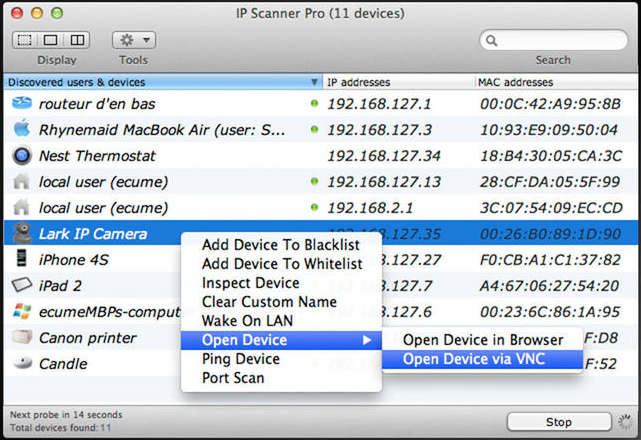
The image above is an example of how the application looks like this one is one button just hit start and it will display the devices that are connected to the PoE switch.
We also provide a free tool that is for configuring your cameras “Configuration Tool” you can use it to find any IP cameras in your network.
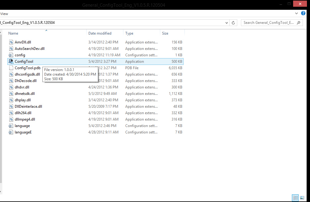
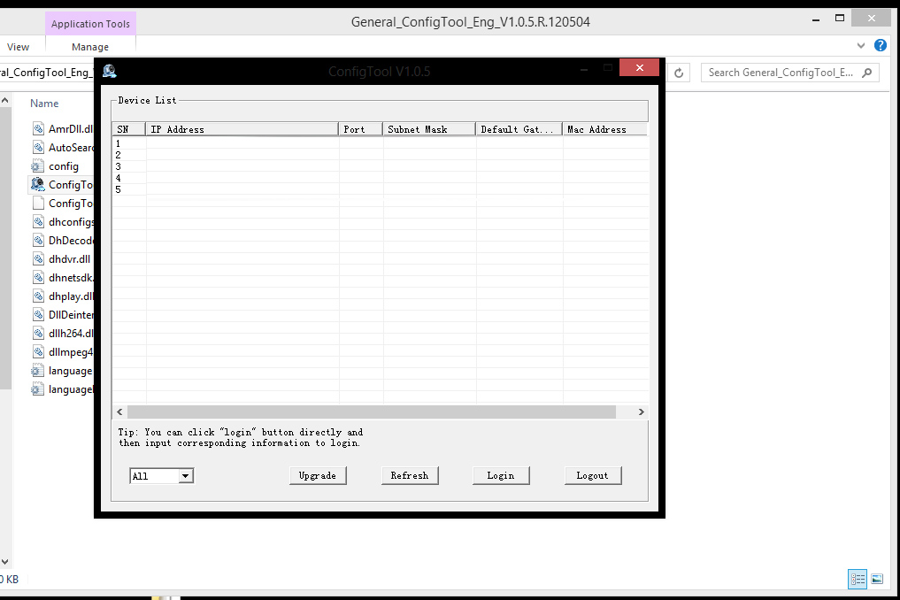
If you are going to utilize our Configuration tool here are some images that will help you launch the application, Make sure to unzip the folder before launching the application. Once you launch it it will display the cameras in the PoE Switch.
Then simply navigate to the correct IP this will allow you to connect to the cameras directly without the need to attach them to an external PoE switch and connecting this switch to the network that the computer is on.
A Simple trick I picked up while getting frustrated after I only had an NVR with Built in PoE and no other way to power the camera separately other than the Built in PoE switch and I needed to access the camera directly to make some changes. There is a little bug that this might only work with a router attached to the NVR itself.


