Prevent tampering on your new TechPro Security Recorders & Lock Boxes. There are times that a bit of security for your security equipment is needed more than the normal Lockbox or locked room, these can be easily accessed by someone with lock picking skills or having access to bypassing tools to gain access to these devices. In these cases they can alter or damage the equipment in order to do their nefarious acts. For this I have a simple solution that will provide you with alerts via email, audible alerts from the built in recorder and/or an external alarm connected to one of the relays built into many of our recorders.
Lets start by gathering what we need.
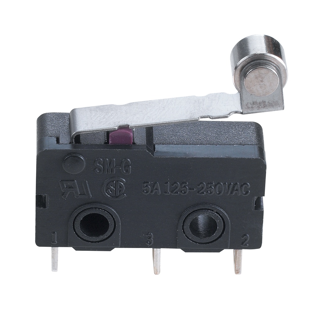
We first need the Micro Switch that will be used to trigger the signal.
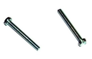
We also need screws (Check Size for best fitment) I used the nut and bolt solution.
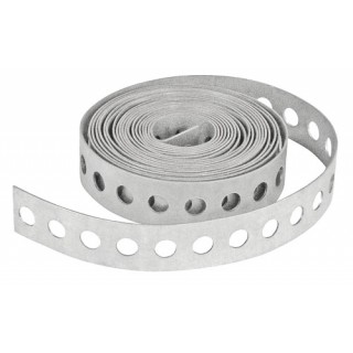
Here is Duct Strip for mounting the sensor in the best spot you can find.
We will also use 18 AWG cable. 
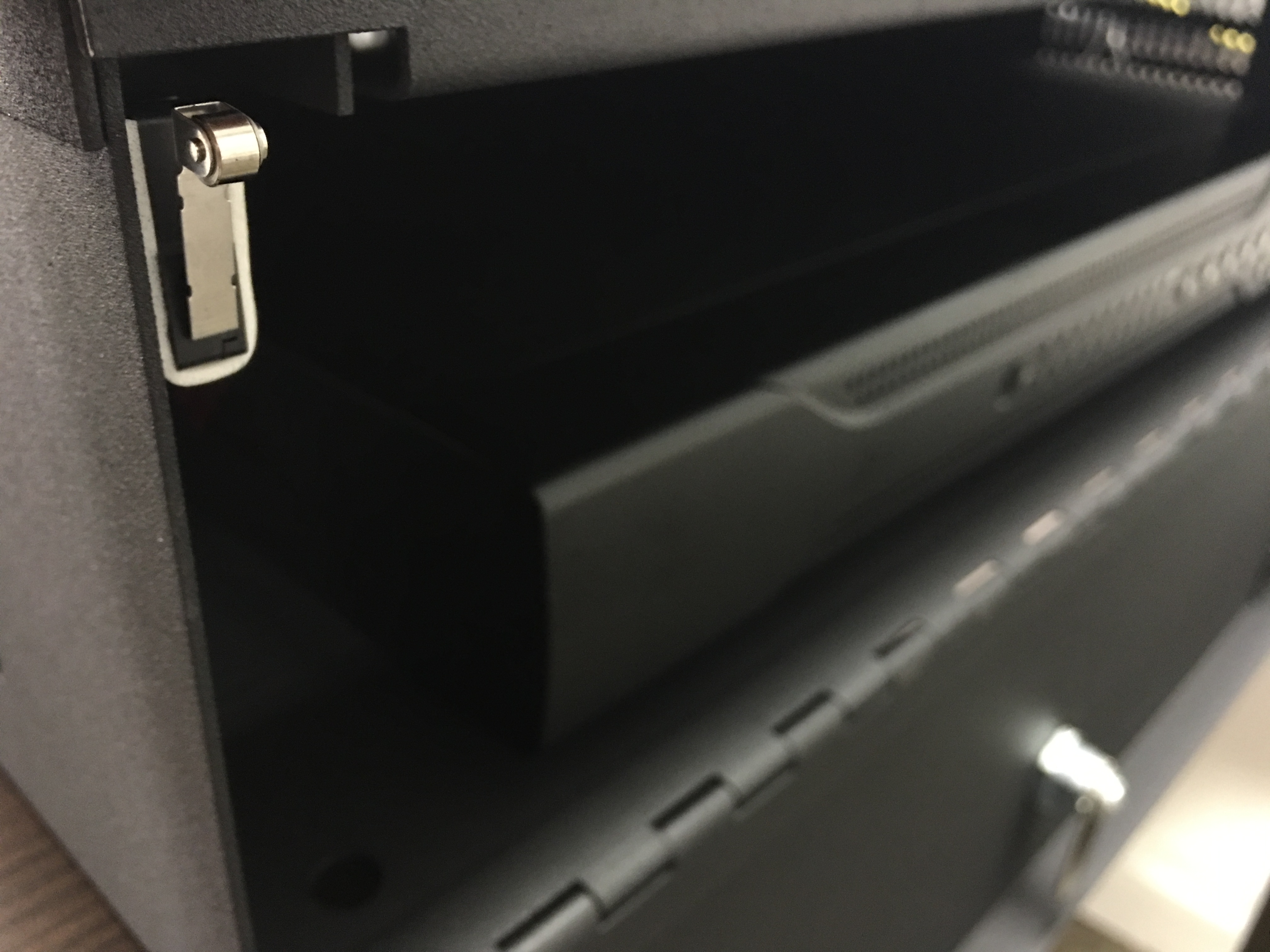
Now the position of the sensor depends on the recorder itself. We carry a variety of options to choose from and one is the Prime Series that has a lid that needs to be slid back to remove the top and vice versa when locking it, this is why we are utilizing the Micro Switch with a roller so that the roller helps with the lids movement without causing any harm to the lid or the switch itself.
Locking the recorder with a sliding Lid.
Unlocking the recorder with a sliding lid.
Once we have found the perfect position so that the roller and the lid have enough clearance and no other parts are touching, we can move on to choosing what type of circuit we will be using. You can choose a normally open or normally closed circuit. For our purpose I suggest a normally closed circuit. This way, if the leads that are going back to the input/output are cut or tampered with, the circuit will open and send an audible alert or an email if you choose to receive them.
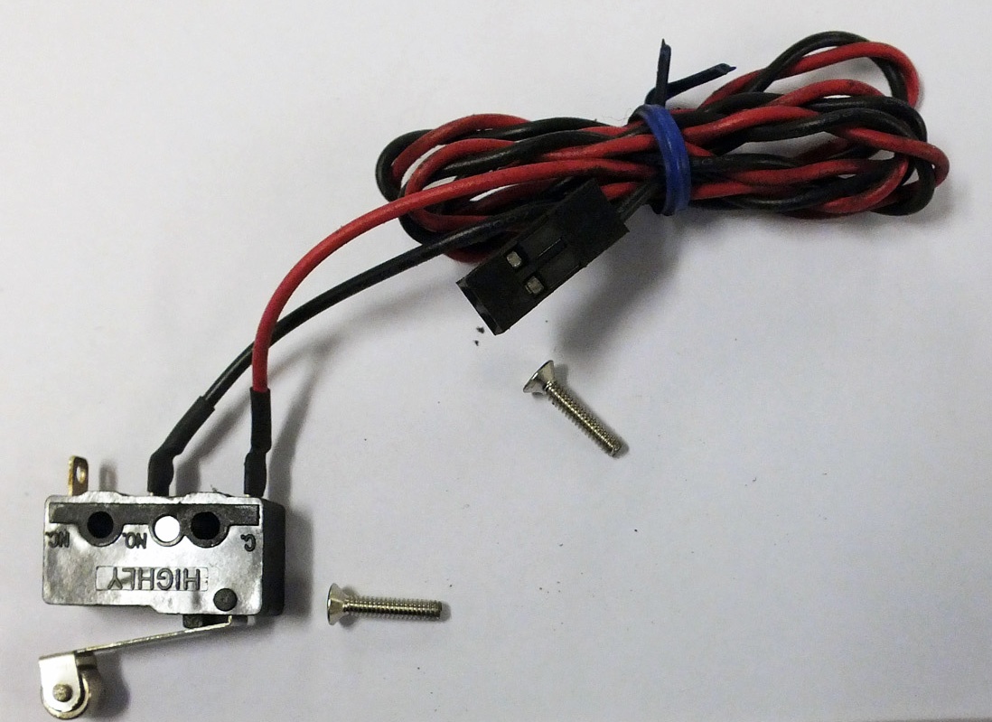
This is an image of an older project with the same switch. This is what we are going to do but in this case we will have one of the leads on the normally closed pin instead of the normally open pin like this image illustrates. 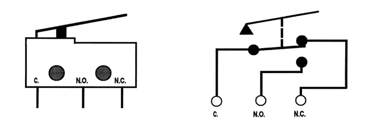
Micro switches are very popular. It basically has a common connection and a N.O and an N.C that send the voltage from one pin to the other with the mechanical input of the arm which in our case has the roller ball attached to it.
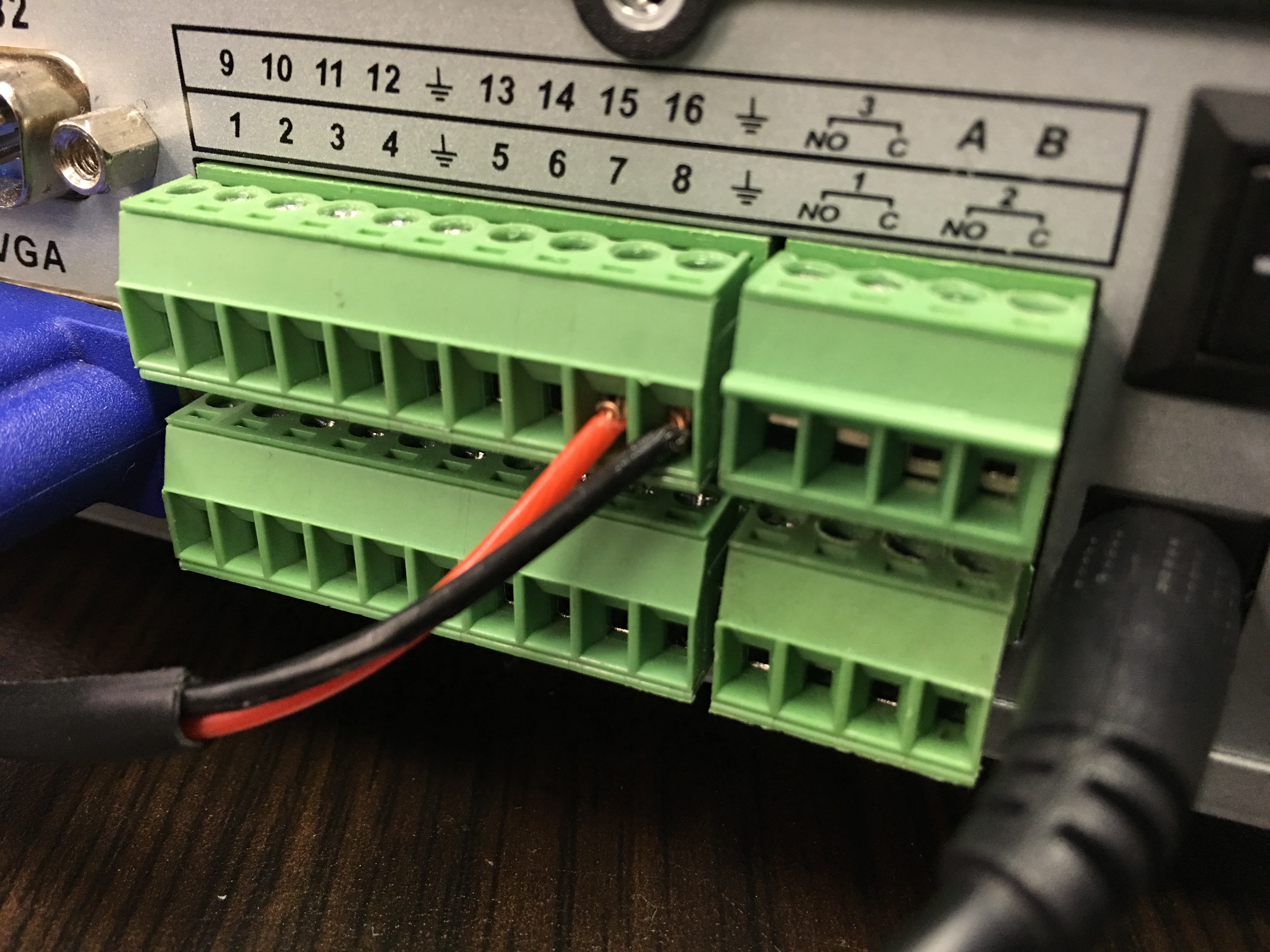
In the above image we can see what terminals I will be using for this demonstration. The black lead is going to the ground/common and the red lead is going to input number 16.
We run the leads as best as possible into the case of the recorder, there are many holes you can choose from. If you choose to, you can make a better connection inside of the unit by soldering the leads to the common and input of your choice. Ensure that the terminal block has these blocked by either filling the block with epoxy or simply cutting the block itself.
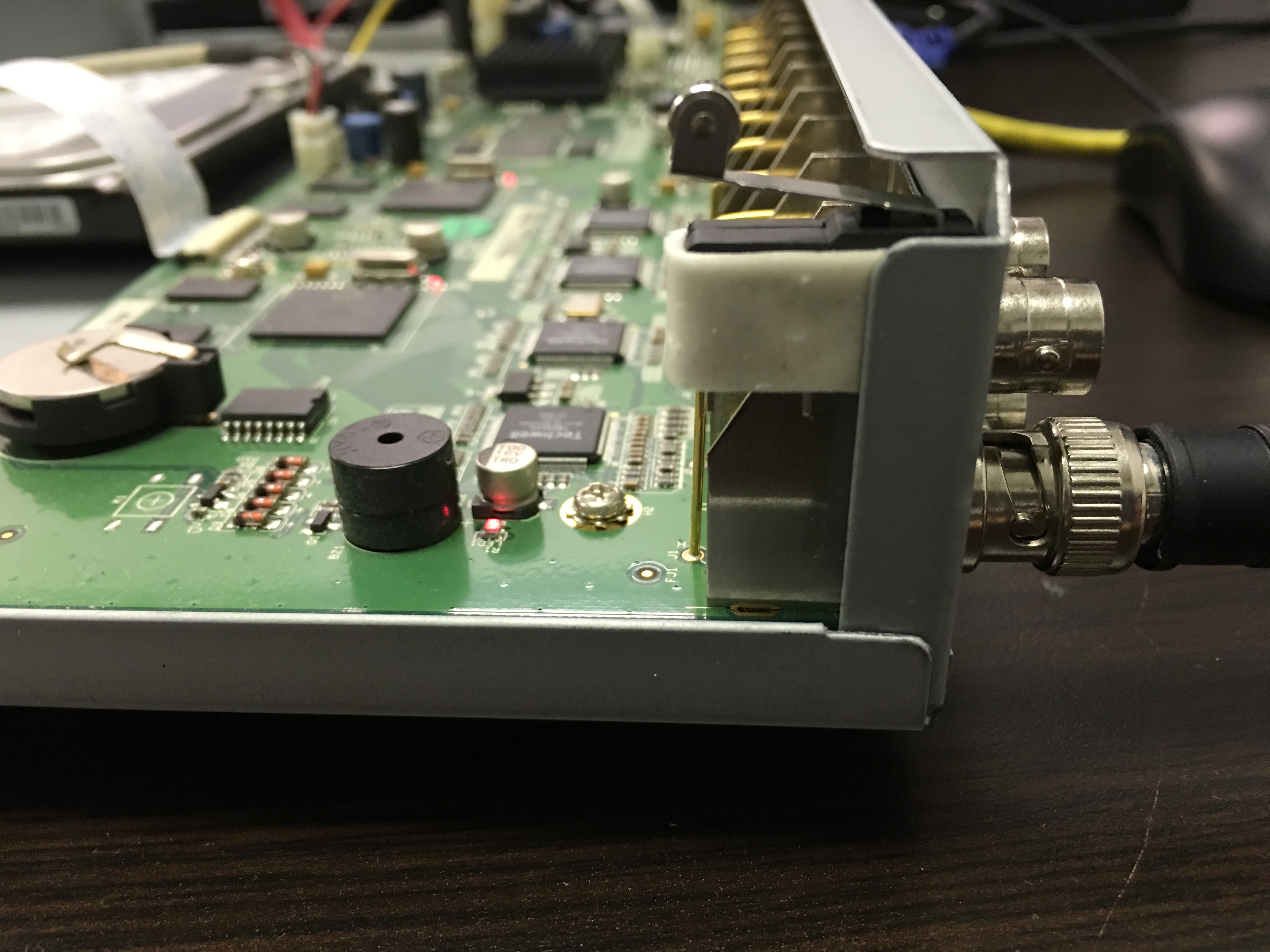
Here are some images where you can mount the micro switch on a CVI Recorder , now I utilized some 3m double sided tape just for this demonstration. If I were to add this I would counter sink the hole that already exists there adding a piece of strap to that, connect the strap to that hole with an angled screw so as to not interfere with the lid and then add the micro switch to it.
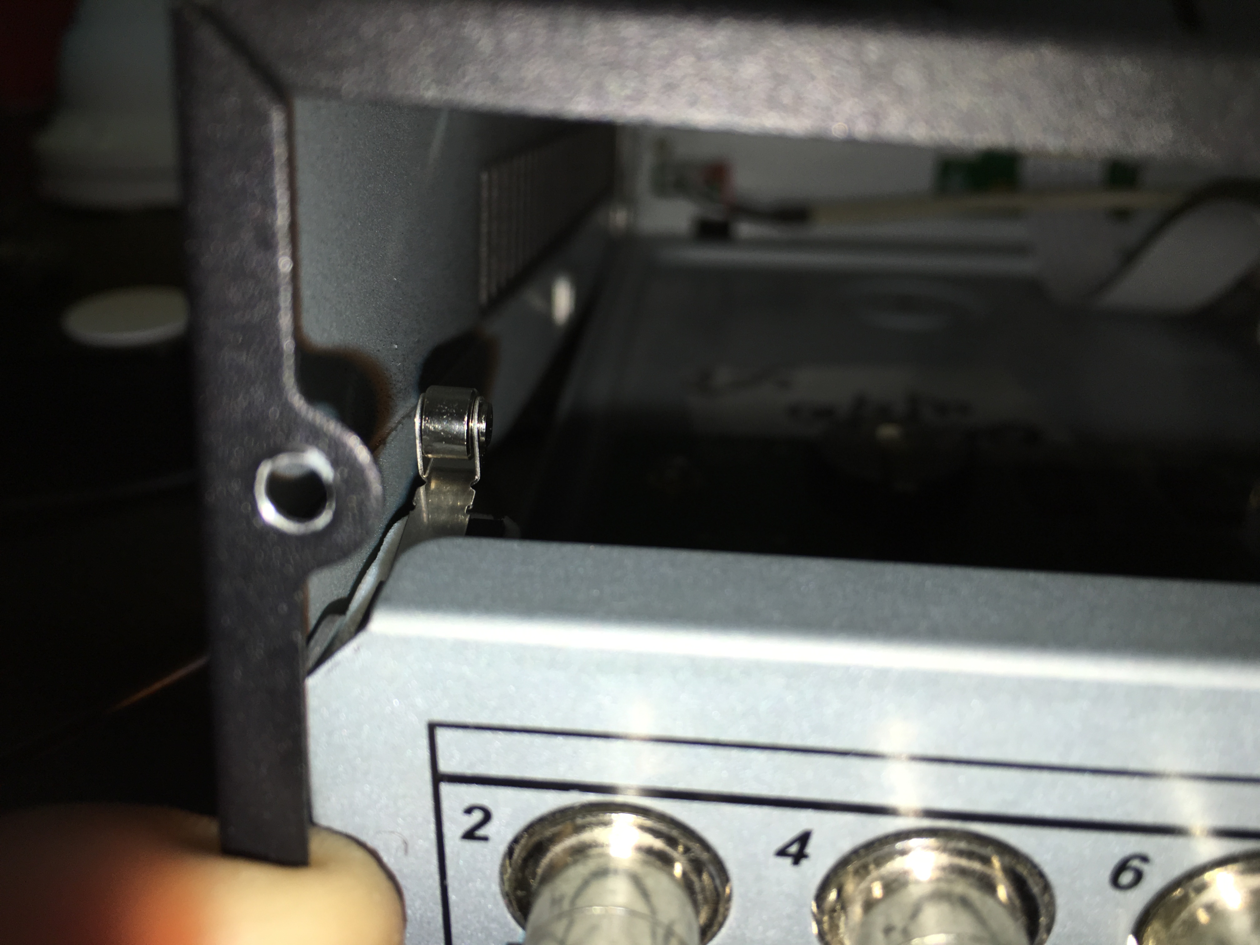
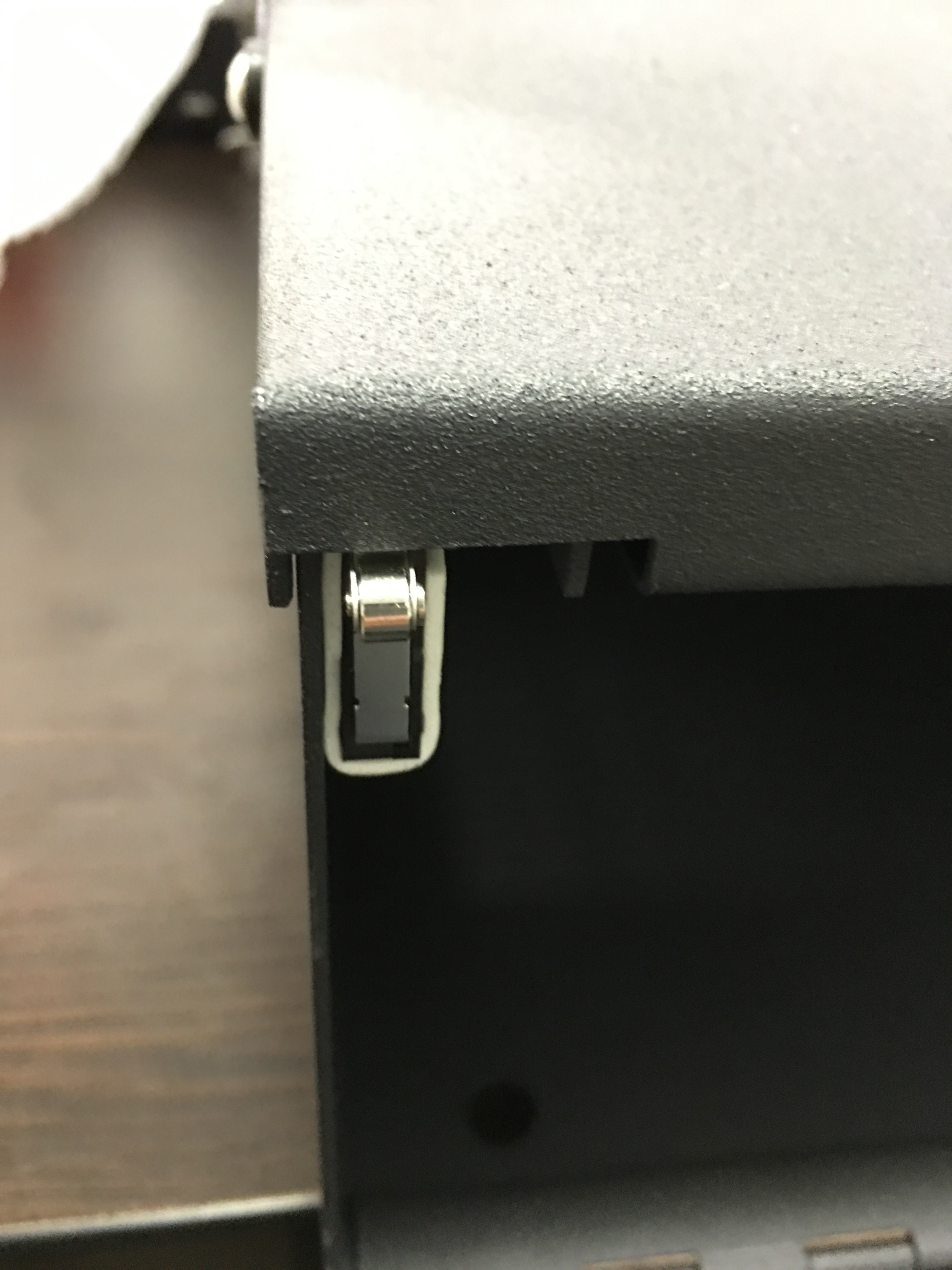
Here you can see the clearance of the switch with the lid.
In this video you will see the switch in action. I am doing some steps before turning the recorder and ensuring none of my test leads are touching the case . I used an LED flashlight I got for free when I purchased the micro-switch at Radioshack since the ones I ordered online were delayed and there was an immediate need for these.
We can do the same with a lock box as shown here.
Now that we have the recorder working with this setup , we need to configure the recorder so it sends us an email, beeps and operates a siren if you choose to add it. In the case of the lock box you can mount the strip to the top lid as the side lid is the first thing that needs to be opened.
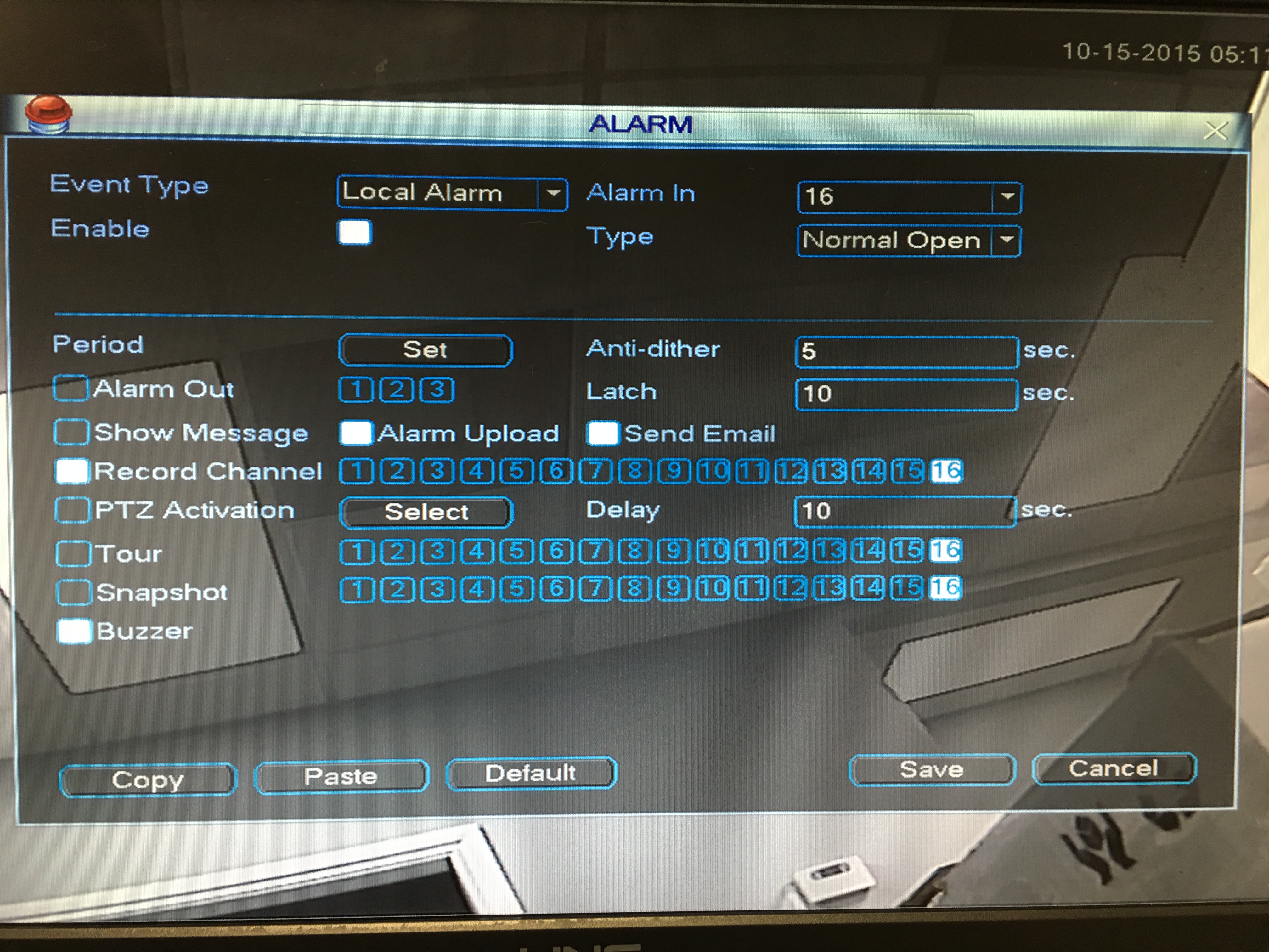
I had to switch to an analog recorder since I was not able to make any changes to the other without changing what was there already. For any other recorder it is similar to this Go to the ALARM section and under “Event Type” select “Local Alarm” and check the box with the label “Enable”. Next, select the number of “Alarm in”, in this case we are setting it to 16 and we are just looking for a beep to ensure it was functioning.
For Email, check the box labeled “Show Message” and then check “Send Email”.
For Snapshot (saves an image from the camera that is near the recorder) make sure you select the correct channel here.
Buzzer, will enable the internal buzzer. (not as loud as you would think)
Alarm Out, this is where you can add the rule where a siren can be installed. When using this, add the siren and use the common and other to the 1,2,3 outputs. (This will turn on the siren when the micro switch is triggered)
Save this and you are all set unless you want an email. In this case you will need to do the following:
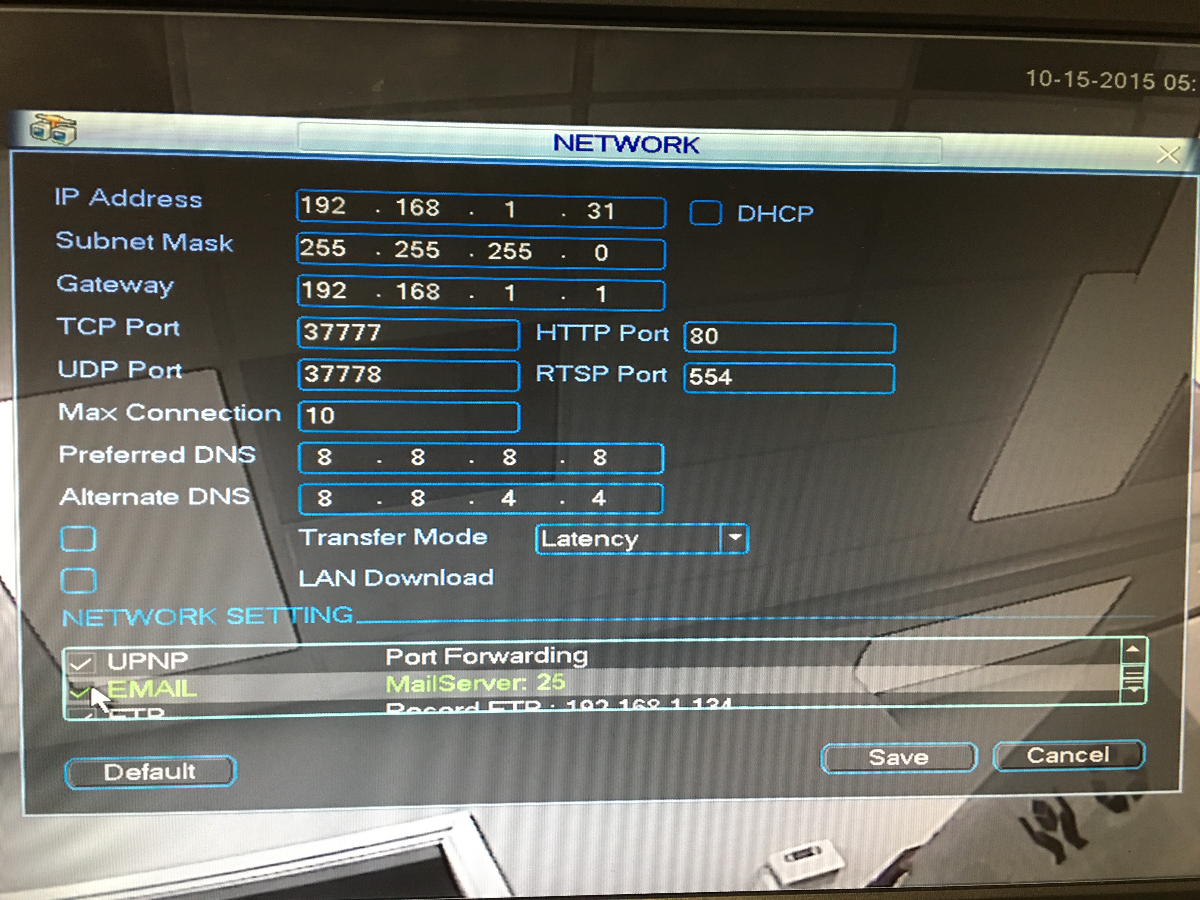
On the bottom of the NETWORK page you must pick EMAIL to enable Email, and then double click on the word “EMAIL” and this will bring up another window where you can add your settings for email output.
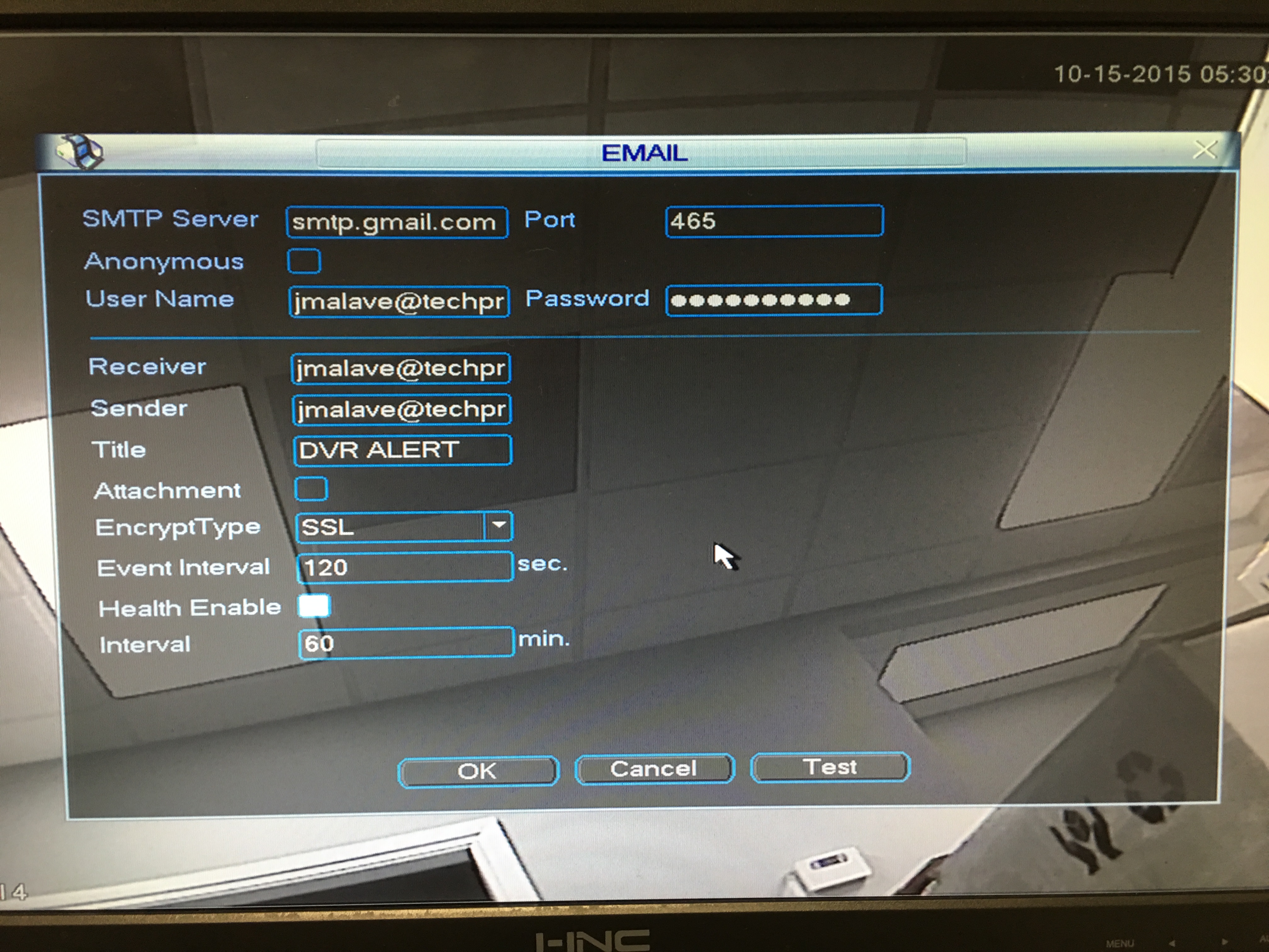
In my case I am using the Gmail Servers. Make sure you select Port 465, add your username and password, and select SSL Encryption. Everything else is self explanatory. Once the recorder is tampered with your will receive an email and any other notifications or alarms . You can select the title of the email to reflect something like ” Recorder Tampered With!”