Almost any Ethernet enabled device nowadays has the ability to be accessible from a computer to configure some or all of its settings. They are running a service that allow us to interact with the device from our PC over the network using almost any web browser.
The service is called Web Service and on certain devices it will be disabled. In this demonstration I will go through how to enable the features and some of the settings of the Web Service of the IDTECK 4 Door and 8 door Access Control Boards.
First, let’s make sure that you know what you will need in order to get this configured correctly.
The following items need to be set first:
Access Control Board: 4 Door Access Control Board or 8 Door Access Control Board
POE+: Get the Single Port POE 30w Injector Here
An Ethernet Cable
A PC with an Ethernet port which is connected in your network as well as the board.
iMDC Emulator V 1.30: Here
First you will need to make sure that the Web service is enabled in the board itself. This is regularly turned OFF because many customers would rather use the Enterprise Software instead. This is due to the fact that using the software will enable you to use many more features than using the web service. The web service will be more user-friendly and is just to get your access control up and running quickly. This is only recommended to be used if you don’t want to install a server with a database and communication server. This method only offers basic settings to get the system going.

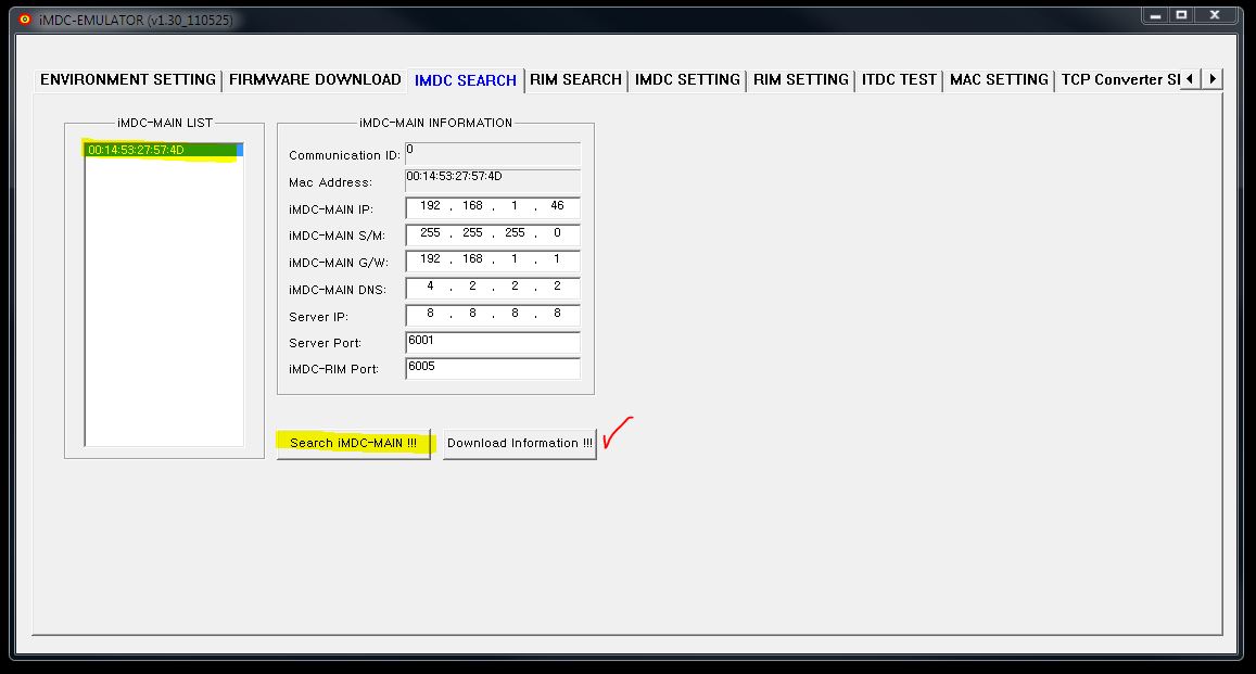
Connect the board to the POE+ and wait until the unit boots up and then open iMDC emulator to find the device in the network. The boot up time is about 40 seconds.
Open the software and click on the tab labeled IMDC Search. Click on the “Search IMDC-MAIN” button and the MAC address of the board should appear. Double click on the MAC address to populate the IP address information in the software. Change the IP address to something that matches your Network scheme and make sure it is not been used by another device in your network. After you have input all of the information necessary, click on the “Download Information” button. Please wait about 45 seconds for the changes to take place.
Proceed to open your web browser. Type the newly created IP address you have assigned to the board and hit enter. You might get a error on your Browser like the picture shown below:
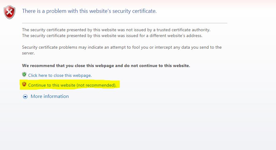
It is absolutely safe to click on “Continue with this Website”, so click on that option and the following page will show:
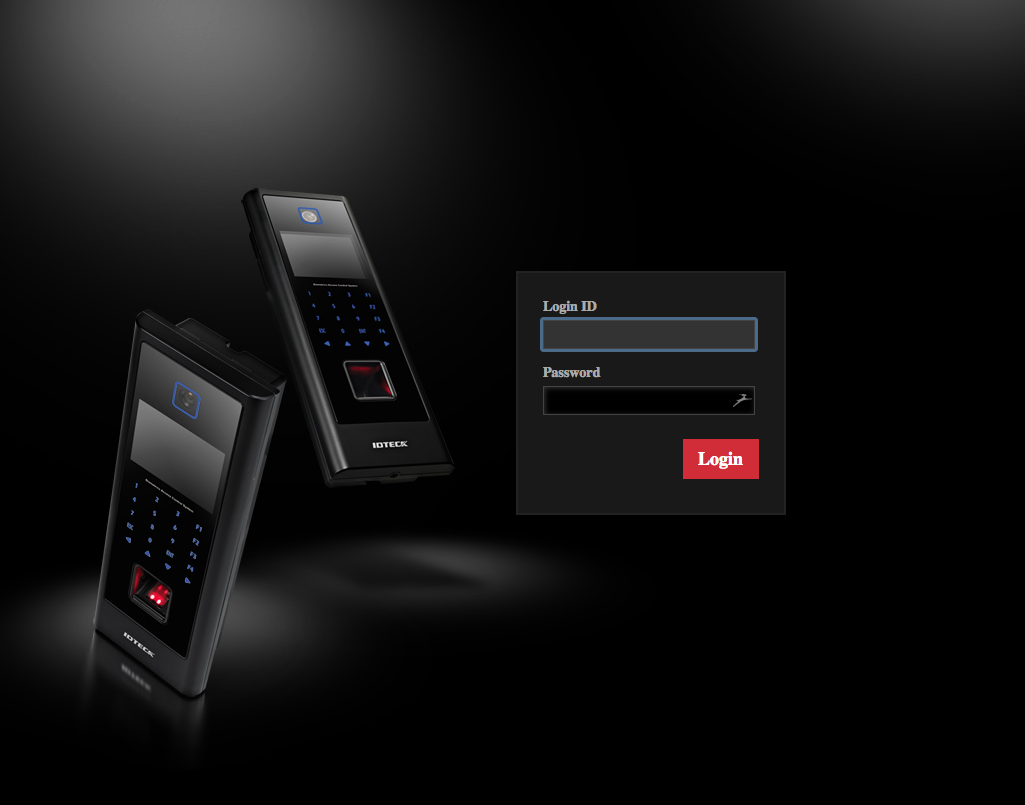
Type the username and password. By default it is “admin” just without quotes. After you have logged in you will be presented with the main menu of the web service.
NOTE: It is recommended that you change the default username and password for the Web Service. Never leave default passwords in devices that are accessible from the network.
Once in the web interface, you can now begin to configure the board. Go to the system tab and make sure your board has the correct language. Also, you can change the device name if you prefer. click on Submit to save the settings. Go to System>Device Settings and be sure the time and date are set correctly.
Navigate to System>Additional Func. In here you can adjust settings such as Time unit setting, Door Open Alarm Delay, and Arm/Disarm Mode. Also, you can configure the Arm and Disarm Code. These settings only apply if the board is connected to an alarm system. Go to Event priority settings to configure what events will display in the event logs. Select the event you are interested in showing through the event logs and add it to the registered priority events window by clicking the arrow pointing to the right. Click submit when done. The initialization tab will allow you to restart the board, reset time schedules, or reset system settings.
To add/register users is easy. Click under Card/Schedule>User Registration. You will see the following page:
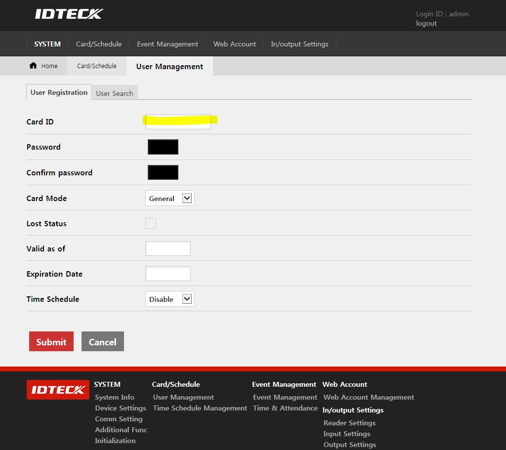
On an IDTECK Card, the last 8 digits will be the ones you will input in the Card ID. The first digits indicate the Manufacturer’s Initials, then the next digits will be the site number. This can be custom made for certain locations where they have different site areas and they will be identified by a number. An example will be having a mechanic’s department were the site number is 200 and the web department site will have a separate site number. All of this can help you administer and manage your personnel more efficiently. Here you can also create a unique password for that card holder. You can set the card itself with a particular mode in which the card can operate. For example, you can configure that card to be a Master card that allows you to unlock certain doors, or you can also assign certain roles based on the position role the card holder may have in the company. In this section you can also set the validity of the card itself from when to when the card will be active. Lastly, you can set up a Time Schedule based on a time slot and have control of what time that car holder will have rights to enter the premises.
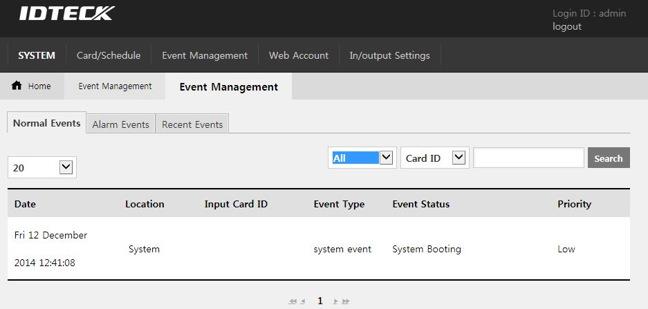
Click on the Event Management to review events such as Alarm events. When someone enters the building and they scan there cards, an invent will be generated. You can select to view up to 100 events at one time. You can filter events by Card ID, ID Event, Input Event, etc.
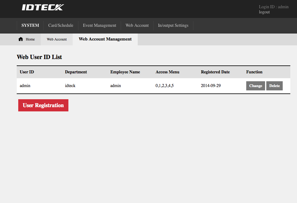
Click on Web Account>Web Account Management to add different web users that will have access to configure this board over the network. Click on Utility to change the session timeout if you want to extend the period of the web interface after it logs out by itself.
Lastly, lets click on the In/Output settings tab. On this tab you will find settings to configure your readers in general. You can force your users to have to enter the premises scanning there cards and typing a password. You can also setup a Duress Code. This is in the event of a person trying to use you to get inside, and by typing this code in the keypad will allow you to open the door but at the same time it will send a covert signal to the access control panel to call your local authority. NOTE: in order for this to work properly you will need to have the access control board connected to your security alarm panel.
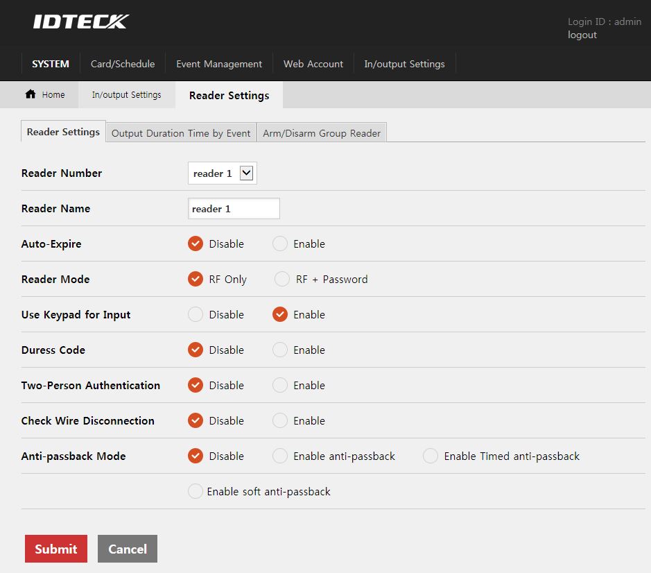
In this window you can also configure Two-Person Authentication when you will need at least 2 cards to open a door or to enter an extremely secure area. Wire disconnection option allows you to log an event if someone cuts some of the wires in the access control board. Lastly, Anti-passback mode, when enabled, prevents someone to exit the premises without having to enter first. For example, if I enter a building that has anti-passback enabled and I give my card to someone to get in the same building using the same door, then the anti-passback will block that person from going out of the building. The reason for this is because he never entered the building using my his card, so when he tries to leave he will not be able to. For this to work you will need a combination of two readers, one on the secure side and another one on the insecure side. Same thing will apply if people that work in this building enter it without scanning there cards. Once they are trying to get out using there card, anti-passback will be activated.
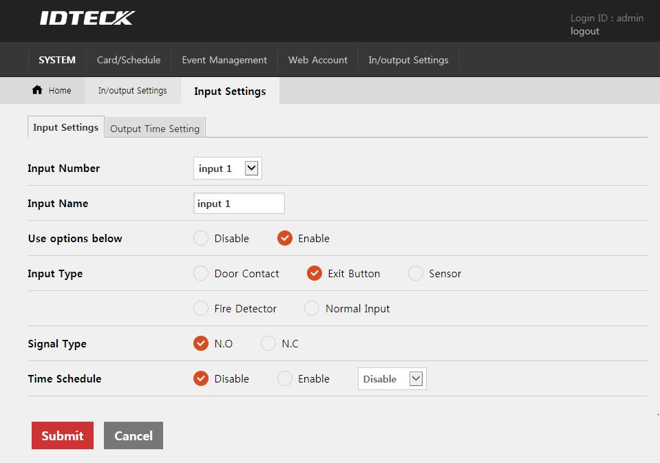
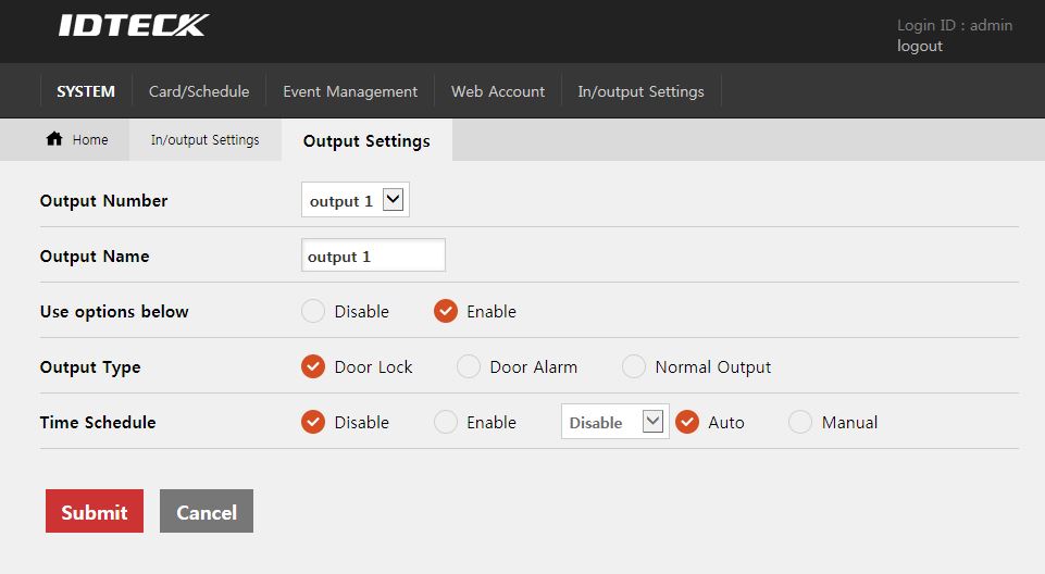
Input Settings setup will allow you to configure the inputs that the board supports. Depending on the model you are using, the input amount will be different. You can set the input type as well, if it is a door contact, exit button or a sensor. Check the right option based on the input device you are using. Also Change the Signal Type, such as NO (Normally Open), NC (Normally Close). Time Schedule is also available for you to enable or disable.
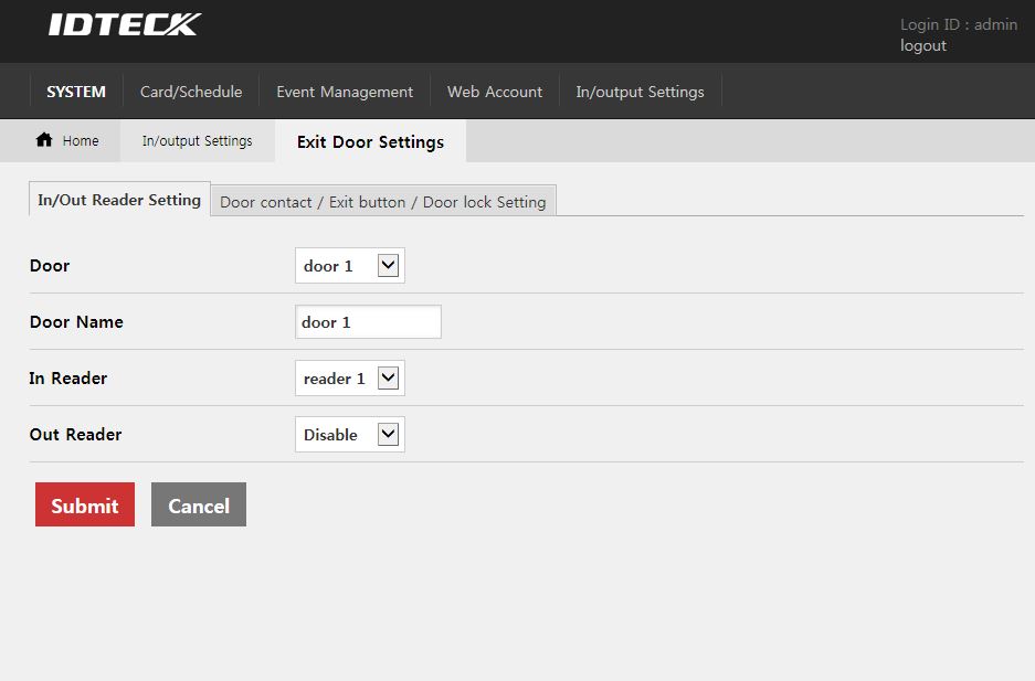
Exit Doors settings can also be configured from this page. Select the desired channel you would like to configure and label the Door Name to easily identify under the event viewer. Assign the correct input channel when installing door contacts or exit buttons.
This concludes the overview of the IDTECK web service access control. For more information visit our IDTECK Access Control Products or our forum