

If you’ve never worked with or around an access control system, it may seem like a complex convoluted nightmare of wiring, circuit boards, card readers, and rather confusing software. In the text to follow, I’ll explain and attempt to remove the mysticism that stands between you and access control wizardry.
One of the most important concepts to understand is that there are 4 basic components in play at every door: inputs, the controller, outputs, and the software.
An input lets the controller know that an event has occurred. For example, someone swiped a card, someone opened the door, someone left the door open, someone on the inside requested to exit, etc… Think of these as the eyes and ears of the system.
Then there’s the controller. Based on how you’ve configured your controller, it will take all the inputs related to a door and determine how to react. Keep in mind, the logic for how to react is usually software configurable. For example, when someone swipes a badge, it determines if it should unlock the door or keep it locked. Think of this as the brains of the system.
All that input and logic is practically nothing without the outputs from the controller. This is typically a relay that either turns a device on, or off. For example, mag-locks, door strikes, alarms, buzzers, lights, etc. The limit to what a controller can use for an output with today’s technology is really limited only by your imagination. Think of these as the hands, feet, and mouth of the system.
Lastly, there’s the software. This comes in many different forms. However, it is extremely important for you to master this component of the system. The software tells the controller how it should react to the various inputs. It also allows you to configure various options. I’ll go into this more later. In the meantime, think of this as the subconscious mind of the system that tells the controller how to react.
Access Control Inputs:
So you have a door you want to control, and you’re wondering what types of input you may want. There are a few obvious choices that come to mind rather quickly. Let’s start with those:
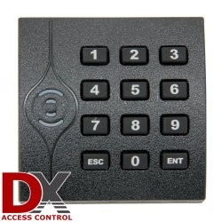
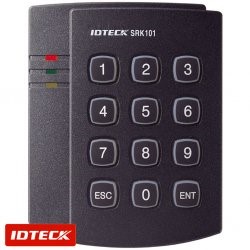
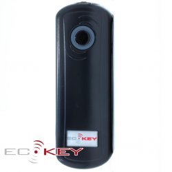
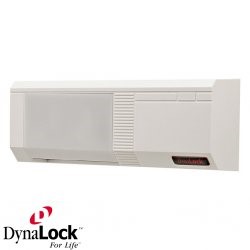
Basic Card Readers:
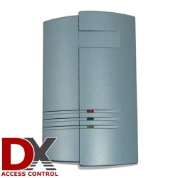
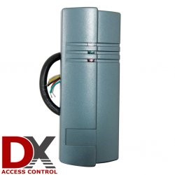
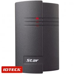
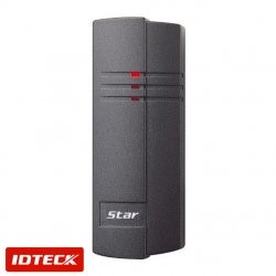
These come in a wide variety of colors, shapes, sizes, and even vandal proofing. However, there are other differences that you will find far more important than aesthetics. For example, it is extremely important that you pair your reader with the appropriate card types. For example in the four pictures above, the 2 brands of readers do not support each other’s cards. Furthermore, within each manufacturer you may find cards that work with certain models of readers and not with others. To make your life easier there are hybrid readers capable of reading multiple types. These are usually a bit more costly and only needed if you somehow ended up with an odd mixture of card types. For the most part, I encourage you to stick with 1 type of card and matching reader throughout your entire organization.
There’s also the protocol with which the reader speaks to the controller. Just like when you engage someone in conversation, it’s generally best if you speak a common language. Just like languages, some readers and controllers can speak in multiple. Among the most common communication protocols (languages) that readers can speak you will find Wiegand with varying “bits”.
While I could bore you to death with exactly how the Wiegand protocol works, I’ll cut to the chase and tell you that the most important factors are that both the reader and the controller are configured to the same EXACT protocol. It is also exceptionally important that they be wired appropriately.
Most readers will have between 6 to 8 wires coming out of them. There are some industry standards for color codes, but ALWAYS consult the manufacturer for proper wiring. Red is usually Positive, but if it’s not you could end up with unanticipated results (and that funny smell of burnt capacitors.) The wires you will typically find are:
DC Voltage Positive +, DC Voltage Negative – (also referred to as ground), D0 or Data 0, D1 or Data 1, Beep or Buzzer, LED control
As I mentioned, these will vary depending on the model of reader. Some may be present, others may not. You may even find additional options.
Advanced Card and Bio-metric Readers:
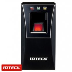
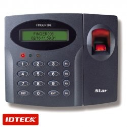
These readers take things a little further than “do you have the right card?” In secure environments you may want to authenticate a person based on something beyond the physical card. For example, do you have the card AND do you know a pin code. You may also have a situation where you need to give access to someone without ever meeting them to give them a physical card. Perhaps you want to allow their cell phone to be their key or just a combination of numbers. Maybe you need extra security and you want an access card to be present, a finger print to be matched, AND a code to be given. The possible combinations are limitless. These advanced readers require a little more effort to configure and enroll your users. However, in the right situations they are definitely worth the extra effort. These typically have the same inputs and outputs as normal readers but they use special programming to configure the additional features.
Request to Exit devices:
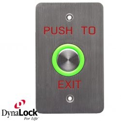
So you’ve got all that fancy reader stuff in place to keep unwanted individuals out. However, you need a way to allow those who have entered the building to exit. Some controllers will allow you to place a second reader on the inside of the door to allow egress. However, in all but the most secure environments, you will find that fire codes require you to allow simple and quick egress. Most installations will require a “Push to Exit” button and a “Request to Exit” PIR/Motion sensor. These devices usually require very limited wiring. Most likely you will need power (commonly 12v DC, but consult the devices manual) and a simple 2-wire connection to the controller. Most commonly the controller expects this circuit to be normally open and will react by opening the door the moment the circuit becomes closed. Many controllers allow you to configure the functionality of this input to be either normally closed or normally open. They may even allow you to specify a delay in reaction time. In addition to the PIR and Push to Exit you can use a wireless relay to toggle door release. You could use almost any device that has a relay to trigger a door event. These devices can be wired directly to the locking mechanism if desired. However, this prevents the controller from logging how the unlocking event was triggered. I only recommend this if you have no need for a record of when someone exited the building.
Door Contacts/Closure Sensors:
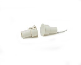
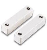
These things are very simple switches that tell the controller if the door is open or closed. This can be useful in certain controllers for triggering an alert or an alarm if a door is left open beyond a specified amount of time. This will discourage people from leaving a door ajar and allowing a potentially unwanted visitor to wander in.
These typically only require a 2-wire connection to the controller and are generally wired as normally closed. If someone tampers with or disconnects the wires from the contact it will consider the door to be open.
Not all contacts are attached to the door in plain sight. Many are built into the locking mechanism. Door strikes often have a relay that senses if the door is latched are not. Mag Locks tend to have a closure sensor that detects when the plate is firmly pulled to the magnet. These make excellent closure sensors.
It should also be noted that you can wire a closure sensor to a buzzer or an LED without the need for a controller. You may need a relay to accomplish your desired result, but the only limit is your creativity.
Access Control Outputs:
So you’ve got all these fancy entry/exit devices in places to tell the controller what’s going on. Now it’s time to give it the ability to interact with the door.
Electronic Door Strikes:
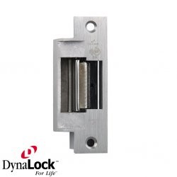
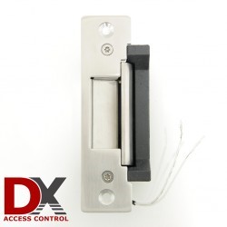
Door Strikes are typically used on doors that have a mechanism that allows egress by simply turning a door handle or pushing on a push bar. These are often used in environments where you need the system to “Fail-Secure”. Fail-Secure means that in the event of a power failure the door should remained locked. Some Strikes can be configured to either “Fail-Secure” or “Fail-Safe” but the most common use is in a Fail-Secure environment. Fail-Safe is the opposite of fail secure, in a power failure the door remains unlocked allowing entry/exit to anyone.
Door strikes are typically wired to the Normally Open side of the door controller relay. This means when the door should be locked, no power is sent to the strike. When the door is supposed to be unlocked, power is applied and the latch is released allowing the door to be opened.
Most door strikes only have 2 wires (for power when activated). However, others may contain a closure sensor as mentioned in the Inputs section. This makes the strike both an input and an output device for the controller.
Mag-Locks:
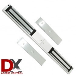
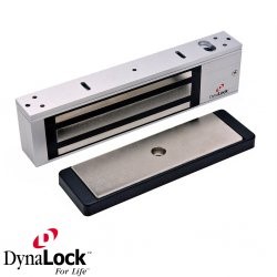
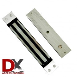
Mag Locks are large electromagnets with a lot of force. They commonly come in 600lb, 1200lb, and 1500lb of pull strength. The amount of force that would be required to pull a door open is not something a normal person can achieve easily. This makes them ideal for a locking mechanism. Although they are usually fail-safe devices as they only have strength when energized with electricity.
Mag-Locks typically only have 2 wires that need to be attached to a Normally Closed relay on the door controller. This means that when the door should be locked, the circuit remains closed and power flows to the mag-lock. When the door should be opened, the circuit is opened blocking the flow of power and releasing the magnet.
Many mag locks will also have closure or bond sensor which can report the door status to the controller. This would make them both an input and output device if used.
LEDs, Buzzers, Sirens, DVRs, NVRs, Alarms, The endless possibilities:
Controller boards can be used to control a wide variety of equipment. Usually this is done through the door relay or through an alarm condition relay. It is important to note that you may need to use an external relay (as in not the one built on to the board) if the voltage of the device your trying to control differs from the other devices the on-board relay is controlling.
While it may seem complicated, it’s very simple. A relay is a switch that is controlled by another device. If you apply power to a relay, it switches from its “Normal” state to its “Abnormal state”. If you wire a device to “Normally Closed” then it will allow electricity to flow to the device until power is applied to the relay at which point it will stop the flow of electricity to the Normally Closed side. Conversely, if you attach a device to the “Normally Open” side of a relay it will prevent the flow of electricity to the device until power is applied to the relay, at which point it will allow the flow of electricity to the device.
With that being said, you can wire almost anything to a relay. Some common uses you will see include LED’s and Buzzers to alert that a door is open, an input on a DVR/NVR to trigger the taking of a snapshot or video of an event, connection to an alarm system to warn of after-hours door openings, etc… again, the possibilities are limited only by your imagination and willingness to wire in the devices you want.
Network:
It is also worth mentioning that many controllers support connectivity to a network. They can use this for outputs. Such as sending an e-mail when a door is left open or when a disabled card attempts to gain entry. Consult the manufacturer of the controller to determine what your options are.
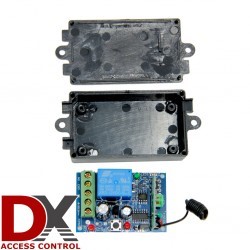
Access Control Boards:
These come in a massive variety of functionality. Once you’ve settled on the manufacturer you like, it’s time to determine what your requirements are. Most commonly this will be determined by the number of doors you need to control and the end users expectations of functionality.
While I could show you a lot of different examples, for the purposes of this document we’re going to look at a single door controller and briefly examine its functionality.
DX Series Single Door Controller:
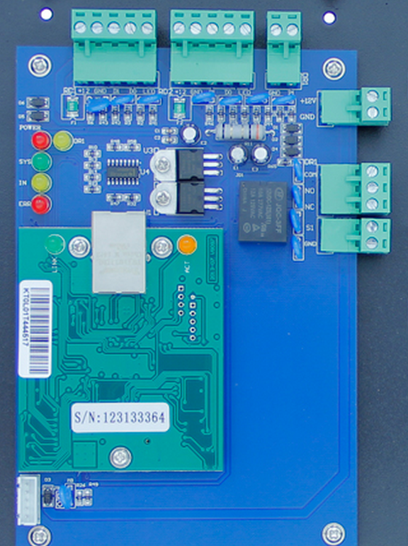
Starting at the top left is a connector for a reader. You may notice, there are 2 of these. As I mentioned previously, you can control egress in certain situations by placing a reader inside the door. This controller allows for 2 readers at a door. This is not a requirement, 1 reader is sufficient per door in most cases. The pins on this board for the reader are as follows:
+12 = Positive (+) 12V DC
GND = Ground or Negative (-) 12V DC
D1 = Data 1 (One of the two connections that Wiegand uses to communicate)
D0 = Data 0 (The other connection Wiegand uses to communicate)
LED = Controls the LED on a reader to let people know they were granted access. This can also be tied to the beeper or buzzer in a reader to give an audible sound or both to provide audio and visual indication.
The second reader connection is the same as the first. So I’ll skip the second 5 pin connector.
The 2-pin connector facing up is intended for 12V DC power for the board
The 2-pin connector facing to the right near the top is for the door contact or door closure sensor.
The 3-pin connector is a relay for controlling the outputs at the door. Remember, unless otherwise told by the manufacturer, you should wire mag locks to the N/C or Normally Closed side of the relay and Strikes go to the N/O or Normally Opened side of the relay. The common goes back to whatever polarity of power is needed to activate the device.
And the bottom right facing connector is for your push to exit/request to exit devices. You can tie multiple devices into this allowing the door to be released in a variety of ways.
This board also contains an RJ-45 jack (difficult to see from this angle, but it is the silver box looking component near the center of the board. In this instance the RJ-45 is for connecting the controller to a network for programming. It should be noted that there are some controllers on the market that use RJ-45 connectors for low voltage and not just data communication, you should always consult the manual before connecting one of these boards to a switch or other networking equipment.
Access Control Software:
Software is an area that I will only briefly discuss because this is probably the most diverse area of an access control system. Some controllers use built in software on a web interface, some require a computer running a commercial piece of software, and still others require Enterprise class software with large scalable database support. Make sure you understand the needs of your users, the capabilities of the software, and the requirements of the software before purchasing a controller. Software prices range from free to extremely expensive. So make sure you factor this into your design.
At its core, the software is usually merely a method for telling the board what users get access to which doors and at what times. This can come in the form of adding a card or setting a pin.
Depending on the controller, the software may also provide additional features such as setting egress delays, or specifying alerts via e-mail, or even changing the way inputs/outputs work. Keep in mind this will vary between manufacturers, controllers, and software options.
More advanced software can provide additional functionality such as time and attendance reporting and integration with CCTV or alarm systems. Consult your manufacturer for an accurate list of features and functionality.
The End:
While there are additional aspects and details that can be involved in access control, We have covered the basics of an access control system and the interactions of the various components.


