

Many customers have contacted us to help them with their access control needs and sometimes it can be cumbersome to explain. In this article I will show you How To Wire an Access Control Board. I will use our DX Series 2 Door Access control Board (ACP-DXEL2), a Proximity Card Reader (ACR-DXRF01), an electronic door strike (ACDS-DX1500SE), 22-8 wire and a power supply with at least 3 or 5 amps.
In this article I will cover the steps to wire the electronic door strike and access control reader to the board and test the system.
Note: In order to make the system work, our Free Access Control Software needs to be installed in your PC. You will need to program the Access Control Board in the software, create a user, and assign at least one card to that user. Also, it is necessary to create at least one zone in the software to properly identify in the logs which door has been triggered.
Lets look at the components we will be using:
2 Door Access Control Board – DX Series

Weather Resistant Access Control Reader – DX Series

Fail-Secure Electronic Door Strike – DX Series

If we take a closer look at the access control board you will noticed certain labels on each of these terminals. On some access control boards you will have two reader inputs per door terminal and a push to exit input as well. These two reader inputs are there if you want to use a reader to exit the secure site of the room without using a push to exit button.
The first setup I will do is the wiring of the power supply I will be using. I’m using a 12V 5amp power supply and from there I will be using a distribution block to run my power to some of the components. It also keeps it clean when explaining the wiring.
This is another diagram that shows where each device goes where:
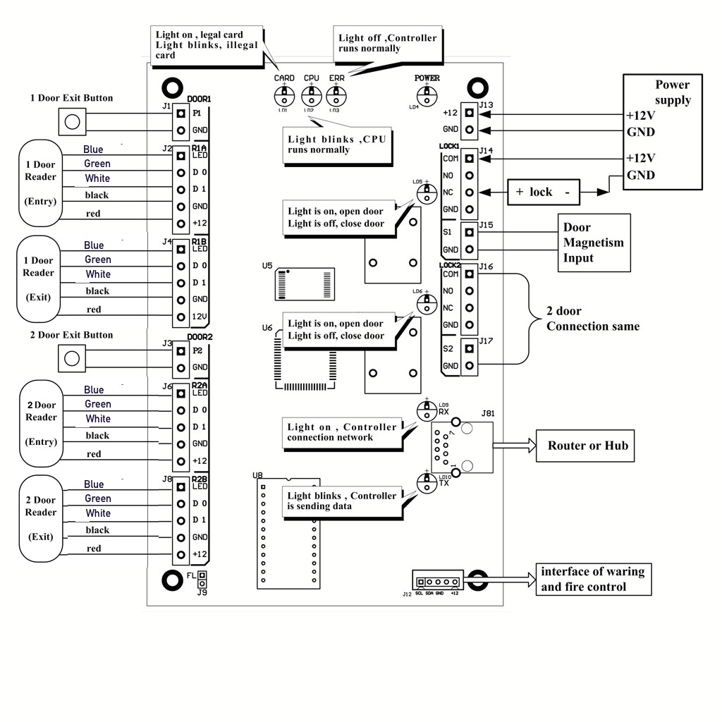
Looking at the diagram we can see that there are two reader ports in this board per door. You can also see the outputs (Door Strikes, Mag-locks) and other ports such as Ethernet and the fire controller port.
I will explain the wires on this RFID reader. These readers have 7 wires. Each wire is colored and is important to know where each of these wires go where.
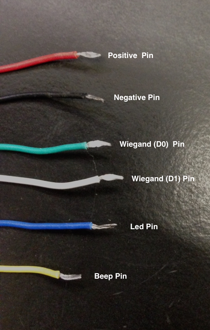
These are the wires that we will need to connect to the access control board. The last two cables can be connected together and connect to the LED port of the Board. Having these two cables together will basically make the “beep” and the light work the same as the sound. In other words if the sound is 2 beeps then the light will blink 2 times along with the audio.
The red and black cable are very important to be connected correctly and not crossed, otherwise it will damage the equipment and the access control board. The green and white are the data cables (Wiegand). These should be connected correctly so when cards are scanned through the readers it sends the data to board and therefore access is granted or denied.
Power connections to the board and outputs are easy. Lets take a look at the power terminals and relay terminals from the access control board. Depending on the output you use, the connections to the relay terminals could be different.
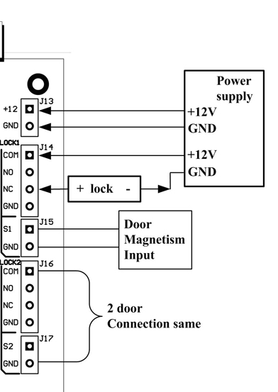
If you noticed from top to bottom, the board has different inputs. The top port will be the power input for the board itself. You will need to run a jumper cable from the 12V (positive) port to the COM port; this will allow the relays on the board to operate.
Also if you pay close attention to the power supply, you could also run the 12V (positive) cable to the COM port directly.
Let’s take a look at the connections of the electronic door strike. Usually strikes are Normally Open (NO) devices. Normally Open devices (NO) require power to change its state. These devices sometimes are referred to as Fail Secure, as they require electricity to unlock. For this demonstration I am working with a Fail Secure Strike, which means that if the power fails, the strike will stay locked.

This particular strike comes with 2 cables which have no order in how they are connected to the board and power supply. To connect the electric strike to the board, simply run one of the wires to the (NO) port of the Access Control Board, and the other one to the negative port of the power supply. That’s all there is to it.
You could test the connections manually if you login to the board through the web service. You can download this Web Configuration Tool to find the board in the network and enable the web service of the access control board.
After you have set that up, then you can access the access control board by its IP address. The default username and password is abc for username and 123 for password.
Once you have access to the board you can click on “Open Door” to activate the strike and test your connections. You could also configure certain things like door delay, add cards, change the board’s time, etc.
NOTE: The connections in the board are labeled properly. Reader ports will have RD1 or RD2 depending of how many doors the board supports. Also The board outputs will be labeled as well. These can be labeled as DR1, DR2 etc. There are also other ports and these can be for push to exit buttons and door contacts.
If you would like to have access to the board remotely, the only possible way will be accessing a computer on the network where the board is connected.
At this point if you have followed everything in here you should be confident that the system will work after you configure the software. I will be making a Part 2 of this article that will explain how to configure the software, add departments, personnel and upload those settings to the board.
